One can always go very far with all such considerations like here
The Quest for Quiet: Measuring 2nV/?Hz Noise and 120dB Supply Rejection in Linear Regulators,
but it would end up with the product costing much more than the 1kUSD. I think the performance as presented is very good as is for the asking price.
The Quest for Quiet: Measuring 2nV/?Hz Noise and 120dB Supply Rejection in Linear Regulators,
but it would end up with the product costing much more than the 1kUSD. I think the performance as presented is very good as is for the asking price.
I have found sonic differences according to USB cable length and particular type/brand also.Not really, it really took a while to come to the 30cm selection. The difference was very obvious to me.
I also found more solid bass (short cable) and messy highs (long cable).....that translates to LF noise/jitter according to cable length ime.The only thing now is to figure out whether there is a way to more clearly identify the difference though measurements. This is what I plan to do when I get my RTX.
USB Isolator/Power Injector pcb plugged directly into DAC USB input provided best/clearest/cleanest sound ime.
Dan.
I have found sonic differences according to USB cable length and particular type/brand also.
You are absolutely correct.
We agree for the first time.
Some USB cables make a short, snapping sound when breaking, while others produce the more gentle whoosh of individually failing strands.
You are absolutely correct.
We agree for the first time.
Some USB cables make a short, snapping sound when breaking, while others produce the more gentle whoosh of individually failing strands.
🙂
This is actually a technical thread on Jens work....
Jens, did you also test the prototypes for microphonics? For I understand that SMD parts sometimes can be sensitive to shock and/or vibration when soldered onto a PCB..
Since you strive for high resolution in the measurements, microphonics might become an issue under certain circumstances.
Yes, some components are sensitive to shock and vibration. SMD multilayer capacitors with high dielectric constant ceramics are generally rather sensitive. The worst types are probably Y5V and Z5U ceramics, but I don't use those. Even X7R and X5R can generate electrical noise, when subjected to shock/vibration. I do use these types, but only for relatively uncritical supply decoupling, not in the signal paths.
I also use Tantalum and Poscap (Oscon) capacitors for supply decoupling, in many places in parallel with 100nF X7R capacitors. The large capacitors are of course low ESR electrolytic capacitors.
NP0 capacitors are used in the signal paths. And polypropylene for the input capacitors in case of AC coupling.
I have not seen any problems when working with the Analyzer. If I hit it really hard on the top of the enclosure, with the palm of my hand, I do see some noise, equivalent to around 20uV peak on the input.
So I don't think that microphonics will be a problem in normal use. I did of course have microphonics in mind during the design.
Here is a plot showing the IM performance of the RTX. I'm using my set of Victor oscillators. They are all separately battery powered. This is 11.2 KHz + 12 KHz. First is an EMU 1212M with opamp upgrades, second is the RTX. Both use the same ADC. Clearly the analog circuitry on the EMU is not giving the AK5394A its best. The RTX performance is exceptional.
And amazing that it has gone largely unremarked, I'm very impressed, but then I also have realistic expectations of the device's performance.
The performance of the RTX is clearly far superior to anything I have here, and it's also priced at a point where I can save for and afford. When it jumps to its regular price it will be out of price range for me. I realistically expect that it will outperform my Creative X-Fi music (the pricey one, not the little cheap one).
It is my one shot at getting something that I don't out perform with my work.
-Chris
It is my one shot at getting something that I don't out perform with my work.
-Chris
This is specified in the (preliminary) specification provided in the first post of the GB section.
The measurement accuracy is specified as < +/- 0.05dB (+/- 0.57%).
The analyzer flatness is specified as +/- 0.01dB (+/- 0.11%) from 20 Hz to 20 kHz.
Of course this assumes that the analysis SW doesn't introduce errors.
@VivaVee
Calibration is fairly simple and requires only a good voltmeter and a screwdriver. It might make sense to offer both options, calibration by RTX or user calibration (following a calibration procedure).
Regarding recommendation about how often it should be calibrated, this is still open.
Thanks for clarification!
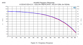
Do you have some kind of frequency equalization built in?
The figure 23 in the AK4490 evaluation board shows clearly that the amplitude at 20kHz is about 0.1dB (1%) lower than at 1kHz.
The datasheet specifies +0.1/-0.2 dB (+1%/-2%) in the audio band.
What voltage reference for the DAC and the ADC do you use and
what is the temperature coefficient?
Is there correction for the gain drift of the AK5394 of 150ppm / °C ?
Do you use thin film resistors and what temperature coefficient?
Is output offset adjustable?
Many thanks,
Udo
Last edited:
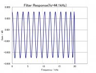
I studied the AK4490 evaluation board in greater detail in the meantime.
My understanding is, that there are two filters inside the chip:
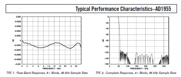
1. the digital antialiasing filter with typical +-0.005 dB ripple in the passband
(first picture)
2. a switched capacitor analog filter to suppress the aliased frequencies.
This filter gives an error of typical 1.8 dB or 23% at 80kHz
(second picture).
I do not want to criticize Jens work.
I want to understand and discuss the limitations and maybe
find ways to improve it 🙂
I also want to make a point that THD measurements below 1 Vrms
are rather useless as the THD goes by definition very quickly to zero if the
level is reduced.
Even my Laptop soundcard has a THD of -140dB at levels of 0.1 Volt 🙂
It is better to use a graph with THD+NOISE over amplitude
(by noise i mean the real physical noise -
not the FFT averaged and rather thing).
Best wishes,
Udo
My understanding is, that there are two filters inside the chip:
1. the digital antialiasing filter with typical +-0.005 dB ripple in the passband
(first picture)
2. a switched capacitor analog filter to suppress the aliased frequencies.
This filter gives an error of typical 1.8 dB or 23% at 80kHz
(second picture).
I do not want to criticize Jens work.
I want to understand and discuss the limitations and maybe
find ways to improve it 🙂
I also want to make a point that THD measurements below 1 Vrms
are rather useless as the THD goes by definition very quickly to zero if the
level is reduced.
Even my Laptop soundcard has a THD of -140dB at levels of 0.1 Volt 🙂
It is better to use a graph with THD+NOISE over amplitude
(by noise i mean the real physical noise -
not the FFT averaged and rather thing).
Best wishes,
Udo
Attachments
Last edited:
One can always go very far with all such considerations like here
The Quest for Quiet: Measuring 2nV/?Hz Noise and 120dB Supply Rejection in Linear Regulators,
but it would end up with the product costing much more than the 1kUSD. I think the performance as presented is very good as is for the asking price.
Why not use a low noise preamplifeir (AD797 or similar) with a gain of 100?
The output of the preamplifier goes to your soundcard or RMS meter.
Put the thing in a grounded metal box and power it with batteries and problem solved 🙂.
Best wishes,
Udo
Last edited:
Udo,
A lot of questions!
I will try to answer some of them.
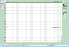
I do compensate, at least partially, the level drop at high frequencies. I just made a loop back measurement at 192 kHz sample rate on an arbitrary unit, see attached.
One channel is almost flat up to above 80 kHz, the other channel drops a bit.
I do of course use thin film resistors. The temp. coefficient are 15ppm for some and 25ppm for others.
The reference for the DAC is the LT3042 LDO.
The ADC supply is less critical since the ADC has its own internal reference. I do not compensate it directly. Changing the supply voltage does not influence the ADC gain.
The output offsets are adjustable. Separate adjustments for each of the 4 signal lines.
A lot of questions!
I will try to answer some of them.
I do compensate, at least partially, the level drop at high frequencies. I just made a loop back measurement at 192 kHz sample rate on an arbitrary unit, see attached.
One channel is almost flat up to above 80 kHz, the other channel drops a bit.
I do of course use thin film resistors. The temp. coefficient are 15ppm for some and 25ppm for others.
The reference for the DAC is the LT3042 LDO.
The ADC supply is less critical since the ADC has its own internal reference. I do not compensate it directly. Changing the supply voltage does not influence the ADC gain.
The output offsets are adjustable. Separate adjustments for each of the 4 signal lines.
Attachments
I studied the AK4490 evaluation board in greater detail in the meantime.
My understanding is, that there are two filters inside the chip:
1. the digital antialiasing filter with typical +-0.005 dB ripple in the passband
(first picture)
2. a switched capacitor analog filter to suppress the aliased frequencies.
This filter gives an error of typical 1.8 dB or 23% at 80kHz
(second picture).
I do not want to criticize Jens work.
I want to understand and discuss the limitations and maybe
find ways to improve it 🙂
I also want to make a point that THD measurements below 1 Vrms
are rather useless as the THD goes by definition very quickly to zero if the
level is reduced.
Even my Laptop soundcard has a THD of -140dB at levels of 0.1 Volt 🙂
It is better to use a graph with THD+NOISE over amplitude
(by noise i mean the real physical noise -
not the FFT averaged and rather thing).
Best wishes,
Udo
The combination of filters is normal practice for delta Sigma DACs (and ADC's). The 80 KHz filter tracks the sample rate. If you look at the pre filter output its pretty clean up to the first image which is pretty high up. I use an LC filter on some of my implementations around the AK4490 which also works well.
In this application (which is measurement) flat response would be the important criterion. The AK4490 allows for the use of an external filter but its unlikely that an external filter would work any better. However the 44.1 KHz clocks may have lower distortion than 48 KHz clocks per AKM due to some optimized internal timing. There are several compromises involved to get this combination to give good results and usually response above 20 KHz is not at the top of the list. However an application with self calibration capabilities can correct for these errors in measurement. Praxis PRAXIS INFORMATION is a good example. I believe there are others.
I really do not understand what you are saying about measuring noise with an FFT? And I can assure you that your laptop does not have a distortion of -140 dB at 100 mV. Distortion products do not by definition go to zero as the level goes down. In DAC's and ADC's they go up as the available bits decrease and the accuracy of the bits becomes a bigger part of the total. Even completely linear devices like opamps can show higher distortion for whatever reason at lower levels.
I do compensate, at least partially, the level drop at high frequencies. I just made a loop back measurement at 192 kHz sample rate on an arbitrary unit, see attached.
One channel is almost flat up to above 80 kHz, the other channel drops a bit.
This is extremely good! I know from experience that it is not easy to get better than 0.1dB flatness over a large band.
Jan
Hi Jens,
Thanks for your great work and the detailed answer 🙂
I aim for a sine generator with a precise absolute level
and flatness over the extended audio band up to 100kHz
(for non audio measurements).
My goal was to get more than 0.1% absolute precision.
To my suprise this it is very difficult as not to say impossible.
I was also surprised to see that the the State of the Art is
not going forward (see attached AD1955 ripple from 18 years ago).
Only marketing improves.
The new Cirrus Logic DAC too seems to target Smartphones
and has no more precision than the older designs too.
@Demian:
How is it possible to switch off the SC post-filter?
This could be a workaround for the 2 dB droop @80 kHz.
Regarding the 140dB THD:
The first harmonic of the THD is proportional to level^2,
the second harmonic is proportional to level^3.
My soundcard has 100 dB THD (not noise) at 1 Vrms level, mainly
2nd harmonic.
If i go down to 0.1 Vrms the level has decreased by a factor 10
and the THD has improved by a factor of 10*10 = 40dB to 140 dB.
So yes, my cheap Laptop soundcard has 140 dB or better THD.
Of course this has no audible benefit as the noise has not improved
and the distortion products are burried deeply in noise
And this was my point: It is very easy to achieve arbitrary low THD
values (the one without noise) by FFT'ing, averaging and reducing
signal level.
But this is misleading as THD+N (THD with noise)
does not improve and that is the thing we hear.
It is more meaningful to specify the output level at say 0.1% THD+N
or use the traditional THD+N plot over output amplitude.
Best wishes,
Udo
Attachments
Hi udok,
No, Demian is quite right.
You are not getting anywhere near the -140 dB performance you are quoting. Try it with a half decent distortion meter and you will see what I mean. Your distortion performance will be limited by the DAC unless you use only one frequency and build a sharp band pass filter behind it, followed by an extremely carefully engineered buffer circuit. The very fact that you will be able to measure distortion above the noise floor of your THD analyser closes the case on this.
I'm sorry things don't work that way, but you absolutely can not achieve -140 dB levels, especially out of an internal sound card in a laptop (or computer). Have a look at the THD vs level plot on the converter your laptop uses. That is the best possible performance that part can achieve, and you will see it falls short.
-Chris
Hi Chris,
Please do not mix up THD and THD+N (after 2nd reading, i think that we speak of the same).
With a classical distortion analyzer you always measure THD+N
and you can not measure distortion harmonics below the noise
floor (and this is the right way to do it in audio).
To prove my point:
Attached is a picture from the AD1955 data sheet,
where the harmonics are clearly below 150 dB, measured with
a very low input signal of -60dBFS.
Maybe this is getting somewhat offtopic 🙂
Best wishes,
Udo
Attachments

Last edited:
Hello Udo,
Where you are wrong is that you refer the THD level to the full scale.
On the spectrum you show, the signal level is -60dBFS and the noise floor about -150dBFS.
SO, you can only say that the THD harmonic are only below -150-60 = -90 dBc !
It is not spectacular !
The dBc amplitude is here referred to the signal amplitude (-60dBFS) not the full scale.
You can also look at the THD math definition that is the ratio of harmonics power
vs input signal.
Hope that is more clear.
Regards.
Frex
Udok-
If you are looking for flat response a soundcard or DAC is not the right way to get there. A good function generator (Krohn Hite for example) can hold .01 dB across its complete range. RC oscillators designed for level performance can also meet that. Above 100 KHz things like cable capacitance interacting with the source impedance will compromise the accuracy. If you need that extreme accuracy look for an AC calibrator. They will have remote sensing. There are special adapters that allow connecting a thermal converter in parallel with your load to ensure extreme accuracy. Useful when calibrating a calibrator. This is all voltnuts territory.
The AC calibrators have low distortion, usually .005% since distortion products can degrade the accuracy. However there is a tradeoff between lowest distortion and amplitude precision.
If all the distortion mechanisms in DAC's (or any device) were completely monotonic your predictions of distortion vs. level would hold but they aren't. The passive components around the DAC in your soundcard will limit the distortion if the DAC were perfect but as the level goes down the intrinsic limits of the DAC get worse. -100 dB SNR is considered very good for laptops. It also means that the best the chip needs to be is 17 bits. Drop 20 dB and you are at 14 bits and the low level stuff becomes dominant.
RC oscillators have different limitations but they are still there. The non-linearities in the level detection and AGC grow as the operating level goes down. no free lunch here.
The best real THD+N performance achievable seems to be around -117 dB at that's only at around 3V. There are a lot of details that converge to limit THD+N performance.
What are you trying to measure? There may be easier and more direct ways.
Hi udo,
Frex and Demian have responded better than I could. I was trying to get across that you are using fewer bits to represent your signal. That will generate harmonics.
The high Q output filter would attenuate your harmonics. It would also attenuate noise as well, but it is the harmonics I was looking at.
There are a few members posting here that know a lot more about low noise performance than I do, and you are at odds with them on this topic. Revisit your logic you used to come to your conclusions and take what they have been saying into account. Then you'll understand better than if someone else explained it to you. Trust me on this.
-Chris
Hello,
Sometimes I think that people are self-limiting.
ADC’s and test equipment are dynamic range limited. Limited both by the limits of hardware and how thin you can slice dynamic range with 24 bit processing. That ~ -117dB number keeps popping up, doesn’t it?
So how can the likes of Texas Instruments claim op-amp distortion test results -30dB better than the limits of the AP analyzers on their test bench?
Take a look at Figure 109 in the LM4562 data sheet.
http://www.ti.com/lit/ds/symlink/lm4562.pdf
By way of R1 feedback is applied to the inverting input of the op-amp. This amplifies the distortion products or another way of looking at it is that the test frequency is attenuated. This technique squeezes an apparently greater dynamic range into the available 24bits of digital processing.
DT
- Home
- Design & Build
- Equipment & Tools
- DIY Audio Analyzer with AK5397/AK5394A and AK4490