FYI Have you read this: http://www.waltjung.org/PDFs/UnivReg_122714.pdf
I draw your attention to the depletion-mode MOSFET current source feeding Walt's regulator. In this situation, a constant current source, a low-power MOSFET can be very good because it needs very few parts (simple and saves space), is very stable and has very high VAF and low capacitance. You would need both N-channel and P-channel parts tho...
I draw your attention to the depletion-mode MOSFET current source feeding Walt's regulator. In this situation, a constant current source, a low-power MOSFET can be very good because it needs very few parts (simple and saves space), is very stable and has very high VAF and low capacitance. You would need both N-channel and P-channel parts tho...
Member
Joined 2009
Paid Member
did they invent depletion mode p-channel yet ?You would need both N-channel and P-channel parts tho...
I'm not very tolerant 😛Look into your heart and decide how many radians (degrees?) of phase deviation you are willing to tolerate.
As there is going to be a bass cut-off somewhere (this is not a dc coupled phono amp) there will be a phase consequence. I just want that to happen at the film cap and not the electrolytic.
It may not matter...the critter won't know which way 'round it's pointin'did they invent depletion mode p-channel yet ?
Member
Joined 2009
Paid Member
as we're looking for a 3d sound stage I was thinking half a steradianwould half a radian be about right?
I have days like that too 😱It may not matter...the critter won't know which way 'round it's pointin'
I thought about this and decided against it. That I use free pcb layout software that is limited to small board sizes doesn't help, but I would rather not have these card-edge connectors. I want the boards to lie flat now too so that I can use pcb-mounted RCA connectors along one side of the board.
I had a thought to do something like this after I picked up a TOA device for a song with the intention of using the enclosure. Each card has a metal back plate (similar to a PCI card) with connectors on it.
The nice thing is you could laser cut acrylic, 3d print, or get metal plates produced - hell you could use FR4 which lets you use a PCB manufacturer/do it with gerbers/EDA tools (for people like me who suck at cad)
The main issue though is finding a appropriate case is not easy and the ones you do find are pretty expensive.
It's too bad there isn't really a standard similar to the 'eurorack' for hifi.
Last edited:
Member
Joined 2009
Paid Member
As I think about wanting to have more than RCA connectors on the back panel I'm returning to the idea of the boards not being with on-board connectors. I have some nice panel mount RCAs that are unsuited for pcb mounting that I might like to use. So the boards are back in the vertical position again and a 'backplane' could simplify wiring. However, this design/project is constantly evolving so if I design a backplane it will either have to be super flexible or I'll be respinning it or I'll have to wait til the end to design one. The latter maybe an option. Thanks for raising this idea again.
As I think about wanting to have more than RCA connectors on the back panel I'm returning to the idea of the boards not being with on-board connectors. I have some nice panel mount RCAs that are unsuited for pcb mounting that I might like to use. So the boards are back in the vertical position again and a 'backplane' could simplify wiring. However, this design/project is constantly evolving so if I design a backplane it will either have to be super flexible or I'll be respinning it or I'll have to wait til the end to design one. The latter maybe an option. Thanks for raising this idea again.
The biggest issue was finding a case that worked without serious modifications and wasn't obscenely priced. A standard off the shelf ATX rackmount case might work but PCI cards are too narrow for even RCA. It wouldn't be overly difficult however to cut the middle dividers and specify a double width.
You can probably get the PCI headers pretty cheaply (or remove them from a motherboard) since they are a mass produced off the shelf part.
Member
Joined 2009
Paid Member
The case is already decided on, to be consistent with my amplifier cases. It's a constraint I have to contend with but then without some constraints my projects wander off....
But it needs Vin to be 8V greater than Vout. The BD140 + GreenLED circuit in post #215 only needs Vin to be 2.5V greater than Vout. Note that the emitter degeneration applied to the BD140 boosts its output resistance quite nicely.I draw your attention to the depletion-mode MOSFET current source feeding Walt's regulator.
BTW parts count is 5 components for BD140, 3 components for Jung. Don't forget to count the gate stopper. It drops to 4_vs_3 if you eliminate the trimpot and assume it's possible to choose a single fixed value of degeneration resistance, as Jung assumes.
_
Attachments

Member
Joined 2009
Paid Member
I'm going to drop the trimmers. I didn't use them in my prototype build (TGM1i) and found it a royal pain because the simulated resistor value didn't match with the real-world voltage drop of the LEDs in my parts bin. To gain some predictability I am replacing the LEDs with BJTs which have well-defined voltage drops so I can pick a target current level, solder in the appropriate resistors and it's done. The BJTs will also mount on the heatsink with the CCS pass transistors and hence provide a stable current flow even when temperatures fluctuate. I think this is a more elegant solution than what I had posted. Sorry, no FETs this time.
Last edited:
The case is already decided on, to be consistent with my amplifier cases. It's a constraint I have to contend with but then without some constraints my projects wander off....
If you are pushed for space you could save a bit by using separate boards for some modules and mount these vertically in your case. If you use board mount input connectors you could fix your RIAA to the back panel.
The power supply has a lot of parts - since you are deriving this from your Naim clone you could look at separating this into two stages and house the first stage in the power amplifier case if this is not fully occupied.
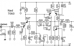
If you look at the Naim preamplifier circuits the input and output coupling capacitors are 10 uF.
There is a perfectionist difference in noise to consider in the choice of capacitor value - the 2k2 low pass network will add to the series input resistance noise of the 470n in your RIAA circuit.
I still have a preamplifier with a 470n capacitor input to the RIAA it was my standard for a long time until the designer published an updated design with dc input.
The best you can do with your input arrangement is to increase the input capacitor value and look to roll-off the low frequency elsewhere. A technique some designers use is to arrange that every stage has a 7Hz low frequency roll off point the effect of this being cumulative.
Member
Joined 2009
Paid Member
I don't fully understand the implications of the 470n input capacitor value on the noise performance and why a larger value is better - is it simply that a higher impedance (at low frequency) implies more noise (as with higher valued resistors) ??
Am away from home. In short yes these elements are in series with that of the input transistor base emitter diode.I don't fully understand the implications of the 470n input capacitor value on the noise performance and why a larger value is better - is it simply that a higher impedance (at low frequency) implies more noise (as with higher valued resistors) ??
the simulation ... didn't match with the real-world voltage drop of the LEDs in my parts bin. To gain some predictability I am replacing the LEDs with BJTs which have well-defined voltage drops ...
Interesting. I did the opposite. I chose two LED types: the green LEDs used by Walt Jung in his super low noise reference (LTL423N), and some red LEDs with relatively low Vfwd (MV5075C). Then I bought 250 pieces of each one and made drawers in my parts cabinet for them. I measured their I-V data and fit SPICE models to my measurements (example). Now I've got SPICE models of LEDs that I know I can trust -- they match the parts that are sitting in my parts drawer.
As Walt points out, this gives a current source with far less sensitivity to temperature than the two-diodes-and-one-BJT current source, and also with far less sensitivity to temperature than the two-BJTs-in-shunt current source. The tempco of the LED very nicely cancels the tempco of the BJT.
Member
Joined 2009
Paid Member
I'm going to start looking at how the parts might fit onto the pcb. This will give me some feedback on what's practical and 'keep me honest' about how many parts make sense here.
The grounding is still not sitting right in my head so I may tweak that as I go.
The grounding is still not sitting right in my head so I may tweak that as I go.
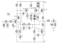
The 8V of that particular part doesn't matter as Gareth has plenty of headroom; he's running the NAD stage at a higher V than is needed. His latest circuit involves more parts: two bipolars and bias components. Current accuracy and drift are not critical in this instance. Also note that the MOSFET floats independent of ground.But it needs Vin to be 8V greater than Vout. The BD140 + GreenLED circuit in post #215 only needs Vin to be 2.5V greater than Vout. Note that the emitter degeneration applied to the BD140 boosts its output resistance quite nicely.
BTW parts count is 5 components for BD140, 3 components for Jung. Don't forget to count the gate stopper. It drops to 4_vs_3 if you eliminate the trimpot and assume it's possible to choose a single fixed value of degeneration resistance, as Jung assumes.
_
Last edited:
Speaking of headroom...
Gareth's power amp psu generates 42V peak at nominal mains voltage. Not sure about Canada but I reckon utility companies typically give +/-10% guaranteed range. So worst case, assuming your house wiring is good and your amp isn't on the same circuit as your arc welder, the peak would be under 38V and down to 37V for the rectifier that precedes the LM317. Then take some more off for the transformer resistance when Gareth is playing Justin Bieber at full wack and maybe it's down to 36V. Then allow 3V headroom for the regulator, so 33Vdc leaving the amp box. If he cracks and uses Walt's elegant, depletion MOSFETs it's down to 25V for the NAD phono stage supply, which seems fine to me.
Gareth's power amp psu generates 42V peak at nominal mains voltage. Not sure about Canada but I reckon utility companies typically give +/-10% guaranteed range. So worst case, assuming your house wiring is good and your amp isn't on the same circuit as your arc welder, the peak would be under 38V and down to 37V for the rectifier that precedes the LM317. Then take some more off for the transformer resistance when Gareth is playing Justin Bieber at full wack and maybe it's down to 36V. Then allow 3V headroom for the regulator, so 33Vdc leaving the amp box. If he cracks and uses Walt's elegant, depletion MOSFETs it's down to 25V for the NAD phono stage supply, which seems fine to me.
- Status
- Not open for further replies.
- Home
- Source & Line
- Analog Line Level
- TGMC - a modular control pre-amplifier