MatLab
Hi Bjørn,
When I called them today they were very helpful.
The MatLab folks are advising me what tool boxes are needed to run your code. They pulled a copy of the M files from the URL you provided here.
To implement API calls from VBA may not require any MatLab Compilations at my end. If this is true, A port to Excel/VBA would only require me to write a preprocessor to convert M file text to the appropriate VBA commands and MatLab API calls to their runtime libraries. I have written parsers before. I will revisit this notion later.
In the meantime I will be exploring horn reflectance for various horn profiles thanks to your generous contribution to my effort. To define horn boundaries I plan on using C-Bézier curves that may be defined to fall exactly on the conic sections as well as other curves of interest like Euler's Spiral (Le Cleac'h). Their use also avoids the introduction of discontinuities in curvature when joining different curves to construct a finite horn. For this reason these curves may also be used in an unified approach to highway design. When driving at high speed on a winding road I can always discern how well the pathway has been designed. I suspect the same is true for the wave traveling in a horn.
Regards,
Bill
Hi Bill,
You're welcome.
I've mainly been using the Academic version of Matlab, which has most of the toolboxes included, so I'm not sure which ones you need. I think my code should run on a bare-bones Matlab installation. Apart from the sinc function which is needed for rectangular horns, and which is part of the signal processing toolbox, but you can easily code that function yourself.
Bjørn
Hi Bjørn,
When I called them today they were very helpful.
The MatLab folks are advising me what tool boxes are needed to run your code. They pulled a copy of the M files from the URL you provided here.
To implement API calls from VBA may not require any MatLab Compilations at my end. If this is true, A port to Excel/VBA would only require me to write a preprocessor to convert M file text to the appropriate VBA commands and MatLab API calls to their runtime libraries. I have written parsers before. I will revisit this notion later.
In the meantime I will be exploring horn reflectance for various horn profiles thanks to your generous contribution to my effort. To define horn boundaries I plan on using C-Bézier curves that may be defined to fall exactly on the conic sections as well as other curves of interest like Euler's Spiral (Le Cleac'h). Their use also avoids the introduction of discontinuities in curvature when joining different curves to construct a finite horn. For this reason these curves may also be used in an unified approach to highway design. When driving at high speed on a winding road I can always discern how well the pathway has been designed. I suspect the same is true for the wave traveling in a horn.
Regards,
Bill
https://ftp.gnu.org/gnu/octave/windows/
I'll give this a shot. I have run Matlab stuff on Octave before. And Octave is free!
I'll give this a shot. I have run Matlab stuff on Octave before. And Octave is free!
Just a bit strange it just seemed to stop working whilst fiddling about with porting an offset driver sim..?
??? Why would you input anything in Vrc when doing an offset driver?
GM
Vrc is rear chamber size in offset horn (OD in hornresp) same as with a normal horn (ND in hornresp).??? Why would you input anything in Vrc when doing an offset driver?
GM
Vrc is rear chamber size in offset horn (OD in hornresp) same as with a normal horn (ND in hornresp).
Ah! Thanks, haven't been keeping up with all the latest enhancements.
GM
EDIT - if there's room for "Inductance Losses" on the Hornresp GUI that would be the best name. It's self explanatory and technically the same thing as "Lossy Le".
Not enough room - it has to be "Lossy Le" 🙂.
I also like the reference to Le for another reason, which hopefully will become obvious once the update is released.
Not Necessarily So
Your time is always far more valuable than that of the tool cost.
Good tools like good employees and good friends, are economic force multipliers.
WHG
https://ftp.gnu.org/gnu/octave/windows/
I'll give this a shot. I have run Matlab stuff on Octave before. And Octave is free!
Your time is always far more valuable than that of the tool cost.
Good tools like good employees and good friends, are economic force multipliers.
WHG
Last edited:
As Odd Ball Said:
"Too Many Negative Waves!"
WHG
Couple of problems with this name (although I do kinda like it).
1. The lossy inductance issue isn't that well known, as I've found out by hanging out at avs forum. Even the people that are well aware of the issue are not using the feature. (Most by far are using WinISD and ignoring my data). As far as I know, only a very few people have used this feature so far. So most people wouldn't intuitively understand "Leach Effect" any better than "Lossy Le". It's a topic that isn't discussed much at all, and before about 20 years ago there wasn't really any reason to consider it because there were no grossly offending drivers wrt to lossy inductance.
2. Leach wasn't the only one to quantify complex inductance, come up with complex inductance t/s parameters and write a paper on the issue. I'm not sure he was even the first to do this.
Even the Leach paper you linked to has Inductance Losses in the title, which is exactly what Ricci and I have proposed - Lossy Le. That's the issue at hand and no other name seems to fit as well.
EDIT - if there's room for "Inductance Losses" on the Hornresp GUI that would be the best name. It's self explanatory and technically the same thing as "Lossy Le".
"Too Many Negative Waves!"
WHG
Your time is always far more valuable than that of the tool cost.
Good tools like good employees and good friends, are economic force multipliers.
WHG
Right now there is more time than money.
On the mend from being quite ill. And your comments and Bjørn's software have me intrigued.
Adjusting Vrc in the loudspeaker wizard and also on the main screen don't affect the graph.
Hi SillySounds,
Is there any chance that Lrc may have been set to zero? If so, then Hornresp would have assumed that there was no rear chamber, and changing the value of Vrc would have had no effect on the results.
Otherwise, I have no idea what could have caused the problem.
Kind regards,
David
Horn Design
I will keep informed as I drill-down into the design issues.
Best Whishes for a Full Recovery,
Regards,
Bill
Right now there is more time than money.
On the mend from being quite ill. And your comments and Bjørn's software have me intrigued.
I will keep informed as I drill-down into the design issues.
Best Whishes for a Full Recovery,
Regards,
Bill
Lossy Le
While the "Lossy Le" code changes have now been finalised, I am currently modifying / enhancing some other aspects of Hornresp, and would like to release all of the upgrades at the same time. Hopefully this should happen in the next couple of weeks.
I also like the reference to Le for another reason, which hopefully will become obvious once the update is released.
While the "Lossy Le" code changes have now been finalised, I am currently modifying / enhancing some other aspects of Hornresp, and would like to release all of the upgrades at the same time. Hopefully this should happen in the next couple of weeks.
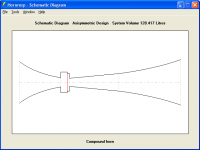
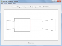
I made Ap1 & lp = 0.
Then go different graph.
Is this ok?
Hi jayam000,
The input data you show in Post #7354, but with Ap1 and Lp set to zero, looks reasonable.
Not sure where you got the screenprint shown in Post #7355, but it is not an accurate representation of your design. The schematic diagram should look more like the attached example.
Kind regards,
David
Attachments
Newbie Questions
Good Morning Folks
So I have spent some time trying to understand speakers and speaker data as best as possible from knowing nothing 3 weeks ago.
I have some basic questions, my apologies if this has been discussed already however with so much being posted it is hard to find everything.
Here are my questions
David, members - I have 2 P Audio C18-Elf drivers with a quoted xmax value of 8mm - though with my understanding as of current this is calculated as Voice coil length - Gap height / 2 which in this case gives me 4mm from rest to peak in one direction thus 8mm xmax quoted is a peak to peak value.
Which do I enter for the use 8mm peak to peak or 4mm?
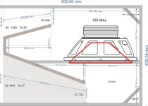
I would like to build 1 of 3 designs being, Tapped horn or folded horn or potentially Scoop which ever may yield the best results. The objective is to achieve an f3 of 45hz to 40hz with a healthy output and safe compression ratio, however every simulation so far my results are poor exceeding xmax even when using 8mm as the value @100 to 150 watts.
is this driver just not meant for these types of enclosure and the nature of the beast is trading power handling for efficiency or is this potentially user error?
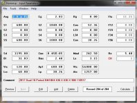
Ts parameters are as follows.
Fs=41HZ
Re=6.1 ohm
Le=0.81mH
Qms=6.76
Qes=0.52
Qts=0.48
Bl=24.76
Mms=198.64
Vas=148.56
Sd=0.12Sqm
Eff=2.01%
Hag=10mm
Hvc=26mm
Xmax=8mm
How do I calculate Mms to Mmd?
Thanks guys!
Good Morning Folks
So I have spent some time trying to understand speakers and speaker data as best as possible from knowing nothing 3 weeks ago.
I have some basic questions, my apologies if this has been discussed already however with so much being posted it is hard to find everything.
Here are my questions
David, members - I have 2 P Audio C18-Elf drivers with a quoted xmax value of 8mm - though with my understanding as of current this is calculated as Voice coil length - Gap height / 2 which in this case gives me 4mm from rest to peak in one direction thus 8mm xmax quoted is a peak to peak value.
Which do I enter for the use 8mm peak to peak or 4mm?
I would like to build 1 of 3 designs being, Tapped horn or folded horn or potentially Scoop which ever may yield the best results. The objective is to achieve an f3 of 45hz to 40hz with a healthy output and safe compression ratio, however every simulation so far my results are poor exceeding xmax even when using 8mm as the value @100 to 150 watts.
is this driver just not meant for these types of enclosure and the nature of the beast is trading power handling for efficiency or is this potentially user error?
Ts parameters are as follows.
Fs=41HZ
Re=6.1 ohm
Le=0.81mH
Qms=6.76
Qes=0.52
Qts=0.48
Bl=24.76
Mms=198.64
Vas=148.56
Sd=0.12Sqm
Eff=2.01%
Hag=10mm
Hvc=26mm
Xmax=8mm
How do I calculate Mms to Mmd?
Thanks guys!
Hi Smashingplates,
Hornresp assumes that Xmax is the driver diaphragm linear mean-to-peak displacement limit in millimetres, which means that 4mm should be used.
In Edit mode, either double-click on the Sd input box and enter the Thiele-Small parameter values, or double-click on the Mmd input box and follow the instructions.
I will leave your question on driver suitability to others more experienced in such matters 🙂.
Kind regards,
David
Which do I enter for the use 8mm peak to peak or 4mm?
Hornresp assumes that Xmax is the driver diaphragm linear mean-to-peak displacement limit in millimetres, which means that 4mm should be used.
How do I calculate Mms to Mmd?
In Edit mode, either double-click on the Sd input box and enter the Thiele-Small parameter values, or double-click on the Mmd input box and follow the instructions.
I will leave your question on driver suitability to others more experienced in such matters 🙂.
Kind regards,
David
- Home
- Loudspeakers
- Subwoofers
- Hornresp