I adopted a ML332 that has some technical issues. The usual failures such as bad main caps are present. There is also evidence of some rather shady repair work on the right channel voltage gain board. Long story short that board has had a major failure and some traces on the edge of the board were disintegrated. Whoever attempted the repair did some real shady point to point soldering with un-insulated tinned wire. They also removed a chunk of the burned area with what appears to be needle nose pliers. Now there is a small jagged chunk of board missing. Not cool at all. The person who did this should be tarred and feathered.
So I am in the market for a replacement board. I am not concerned with the working condition of the replacement. I just would like a nice board to start with and I will troubleshoot the rest later.
Anyone know where I can get my hands on a scavenged board for ML332 right channel? Thanks!
So I am in the market for a replacement board. I am not concerned with the working condition of the replacement. I just would like a nice board to start with and I will troubleshoot the rest later.
Anyone know where I can get my hands on a scavenged board for ML332 right channel? Thanks!
All the hard work is already done. Perhaps, if you ask him nicely, even gerbers 🙂
https://plus.google.com/photos/115831616048330620949/albums/6060334192608013313
https://plus.google.com/photos/115831616048330620949/albums/6060334192608013313
All the hard work is already done. Perhaps, if you ask him nicely, even gerbers 🙂
https://plus.google.com/photos/115831616048330620949/albums/6060334192608013313
Thank you for your response.
I did see Henri's work posted a while back. I made it a point to download all those schematics the minute I saw them as they seem to be a rather rare find. It does not seem like Henri updates that page much but I reached out anyway. Making a new raw board would be really ideal and if he came through that would be great.
I knew taking on this project was going to be an ordeal but to be honest if I can get this amp fired up again I think it would be worth the effort. From an engineering standpoint this thing amazes me. It does not deserve the death blow that it has incurred in the hands of bad techs.
I will be patient. I am sure a board will pop-up somehow and hopefully this DIY community will help me get there 🙂
@Analog_SA:
Henri did return my inquiry. He would not release the Gerber files to the public but also explained how he redrew them (probably in EagleCAD). I know how much that entails so I can't really be surprised that he is keeping them private. If the shoe was on the other foot I probably wouldn't let my work get passed around by strangers either. So I did not get the Gerber file but I got the next best thing. Henri pointed me to an ebay auction out of the Netherlands that had a pair of voltage gain boards. The bidding started at 75 euros and I placed my bid. The auction ended this morning at 7:30 am local time. I made sure I was sitting at my PC at 7:25. No bidders in sight until the last 30 seconds and I sniped it for @ 118.00 euros. So in a week or two I will have two fairly nice boards. I am grateful that Henri pointed them out as I would have never thought to look outside of the US with ebay.
In the meantime I am getting a parts list together for main caps etc. One channel has a resistor burned up so I am going to trace that out and replace any downstream transistors etc.
I would like to know what vendor Mark Levinson uses for their resistors. Does anybody know if they use Vishay?
Sorry nothing to contribute.
But I'd love to see some pics.
Especially of the damage.
Admit it, we all like to see bad work so we can sit back and laugh at incompetent twits 🙂
But I'd love to see some pics.
Especially of the damage.
Admit it, we all like to see bad work so we can sit back and laugh at incompetent twits 🙂
Sorry nothing to contribute.
But I'd love to see some pics.
Especially of the damage.
Admit it, we all like to see bad work so we can sit back and laugh at incompetent twits 🙂
Okay, you asked so here it goes. I bought the amp as a non-working but complete specimen at a fairly cheap price. I will withhold the name of the retailer and the specifics of the deal as they have since refunded a chunk of money and swear they did not know it was like that. I am claiming a monkey could smell what went down in there. They told me they took it in as trade on a Krell.
I went in expecting at minimum some blown transistors and a full re-cap. I did not want a working amp. I wanted an amp that I could bring back to spec and grant it a second life for many years to come. When I took the top cover off I found the following:
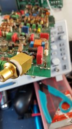
The first picture is beyond words. To begin it is a pure hazard. Second there are missing supporting components (resistors and some melted components) that were not replaced. How they expected this to work is beyond me. The second picture shows how the "tech" did not know how to properly remove an XLR connector shell so he/she just cut the leads. Furthermore the four ground pins on the RCA block are snapped at the board. No amp should be subject to this level of stupid. I would rather see it crushed at the recycle center.
So now I have two replacement boards to work with. I have never worked on a Levinson product. In fact besides a Carver M-400t, that I rebuilt, some Vintage Soundcraftsmen, BGW and SAE gear this would be my first exposure to the esoteric experience of ML. I have always wanted an ML, since first hearing one play at the Audio Saloon in the mid 80's. The ML gear blew my mind but getting married, having kids etc changes priorities. I don't have deep pockets so this may be the only way for me to own one! If I can get it fired up there is a certain sense of pride that comes with reviving old equipment.
Attachments

Last edited:
Thanks for the pics.
Yeah, as you say thats a special kind of stupid.
Wow.
Last board I fixed with a burnt section I epoxied in some new fiberglass before laying new tracks.
That was a smd board 20 odd years ago.
Thankfully boards burnt that bad are few and far between.
Yeah, as you say thats a special kind of stupid.
Wow.
Last board I fixed with a burnt section I epoxied in some new fiberglass before laying new tracks.
That was a smd board 20 odd years ago.
Thankfully boards burnt that bad are few and far between.
Wow. That auction win is worth celebrating. Well done! It beats designing new boards by several orders of magnitude.
Dunno why these amps have such a propensity towards self-destruction. Briefly considered a similar adventure myself, but the dawning acceptance that i can no longer lift even my own bodyweight, let alone dissect such a beast, discouraged me.
Me jealous? Absolutely 🙂
Me jealous? Absolutely 🙂
Attachments
Dunno why these amps have such a propensity towards self-destruction. Briefly considered a similar adventure myself, but the dawning acceptance that i can no longer lift even my own bodyweight, let alone dissect such a beast, discouraged me.
Me jealous? Absolutely 🙂
I once read an article in one of the prominent HiFi magazines, in the 80's, where a gentleman fed a sine wave into an ML mono block and began to use the outputs of the amp to weld some mild steel. It wasn't until I first tried to lift an ML that I understood how that was electrically possible. With what appears to be a limitless current source these amps are a small explosion waiting to happen. As mere mortals, all we can do is try to keep the lightning in check and suppressed. Eventually one day it is going to escape. 🙂
Since I was so fortunate to source the PCB I needed so quickly I decided not to waste a perfectly good thread and continue to post my findings, victories and failures in this, my first adventure, with a Mark Levinson amplifier. Maybe I can get the moderator to allow me to change the title of this thread as it is going in a new direction 
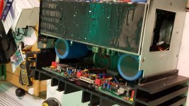
So we all know an amp of this age will have bad caps. I saw it the minute I opened the case. The black ooze that so many ML owners have seen. From what I can tell the amp was stored on its side. The ooze made its way to the top of the amp which does not really make sense. I was spared from having to clean a lot of ooze from the PCB's. Most of it went toward the back panel.New Cornell Dublier caps are on order from Mouser.
I will be waiting for a while for the voltage gain boards to arrive so I will continue exploring the amp as I wait. The left voltage gain board and left current gain board both look to be in decent shape with no visible signs of failure. Even though both current gain boards look good I un-soldered all the output transistors to check them. They all test good.
The right channel voltage gain board is destroyed. I will use that board to salvage small components only. The replacement boards will hopefully take its place without incident.
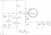
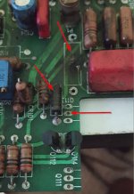
The right channel current gain board has some visible issues. One resistor has over heated and looks like a crisp. I took if out and it still measured the correct ohms. That puppy had a long slow cook. We all know resistors do not spontaneously combust so I begin to look for bad neighbors. Following the traces I see Q113 is next in line. I remove it and it tests good. Hmm. I impulsively pull Q111 and it also tests good. Then I glance at the schematics and I see what appears to be a snubbing zener diode across Q113. It reads current flow in both directions so I guess it is bad and would make Q113 appear to be failed in a shorted condition and that in turn would get the resistors very mad.
I will have to repair the small burn mark area. I have ordered the diode and resistor and am keeping my fingers crossed 🙂
If there are any folks familiar with this board then I invite discussion about things to look out for and other potential failures.
So we all know an amp of this age will have bad caps. I saw it the minute I opened the case. The black ooze that so many ML owners have seen. From what I can tell the amp was stored on its side. The ooze made its way to the top of the amp which does not really make sense. I was spared from having to clean a lot of ooze from the PCB's. Most of it went toward the back panel.New Cornell Dublier caps are on order from Mouser.
I will be waiting for a while for the voltage gain boards to arrive so I will continue exploring the amp as I wait. The left voltage gain board and left current gain board both look to be in decent shape with no visible signs of failure. Even though both current gain boards look good I un-soldered all the output transistors to check them. They all test good.
The right channel voltage gain board is destroyed. I will use that board to salvage small components only. The replacement boards will hopefully take its place without incident.
The right channel current gain board has some visible issues. One resistor has over heated and looks like a crisp. I took if out and it still measured the correct ohms. That puppy had a long slow cook. We all know resistors do not spontaneously combust so I begin to look for bad neighbors. Following the traces I see Q113 is next in line. I remove it and it tests good. Hmm. I impulsively pull Q111 and it also tests good. Then I glance at the schematics and I see what appears to be a snubbing zener diode across Q113. It reads current flow in both directions so I guess it is bad and would make Q113 appear to be failed in a shorted condition and that in turn would get the resistors very mad.
I will have to repair the small burn mark area. I have ordered the diode and resistor and am keeping my fingers crossed 🙂
If there are any folks familiar with this board then I invite discussion about things to look out for and other potential failures.
Attachments
Further progress. I need some advice on something I want to try, please.
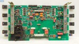
I received the pair of voltage gain boards that I won on ebay. I swear these boards look like they have never been installed in equipment. They were in the original ESD bags with the ML part descriptor label on them. I also installed the blown zener, resistor and output transistor from the right side current gain board. Installed new main caps and now installed bus bars etc to get all caps ready to charge. No heat sinks are mounted. I am doing this because I want to replace other smaller electrolytic caps but I don't want to order those until I am sure I have an amp that is breathing. From what I read in the user manual this amp does not have Class A biasing on the final output stage but has Class A biasing on the stages prior. I cannot run the amp for long without heatsinks for sure.
This time when I first power up with the Variac dialed up to 78 volts the poor variac lets out a loud hum when I press the power button on the amp. I was expecting the initial charge of these four huge 50000 uf caps to be a burden on the variac but I couldnt be sure if it was the caps charging or an actual short loading the variac like that. I cycled the variac on and off a few times to keep the small fuse in it from popping. By the 3rd or 4th time the variac began to quiet down as the caps found a little equilibrium. Both LED'S on the soft start board are now lit and the front panel LED is blinking at 1hz. Good sign! I push the amp from standby (1hz blink) to ON (solid). I hear a flurry of about 7 to 8 tiny signal relays quickly come on in succession. Voila!, the main LED is solid and the amp appears to be keeping all magic smoke within the semiconductors. There are NO output stages mounted though so I am not out of the woods. The other Class-A biased stages are beginning to get warm so I shut the amp down gracefully. I am not touching anything in this amp with bare hands. The power supply sections on this beast demands respect. It can send you to the ER quickly. By putting my finger near the smaller T02 transistors metal tab I can feel the warmth beginning build up.
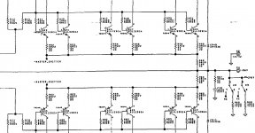
So ultimately here is where I need advice. The final output T03 transistors (24 in total) are out of the picture. I don't want to solder them all in only to find out something else is wrong and then have to unsolder them again. Each channel has 12 T03's. Can I leave 10 of these out of the circuit without fear of damaging anything? I am not going to drive a complex load; maybe just a small bookshelf speaker for testing. I have attached a diagram of how the T03's are configured.
Thanks!
I received the pair of voltage gain boards that I won on ebay. I swear these boards look like they have never been installed in equipment. They were in the original ESD bags with the ML part descriptor label on them. I also installed the blown zener, resistor and output transistor from the right side current gain board. Installed new main caps and now installed bus bars etc to get all caps ready to charge. No heat sinks are mounted. I am doing this because I want to replace other smaller electrolytic caps but I don't want to order those until I am sure I have an amp that is breathing. From what I read in the user manual this amp does not have Class A biasing on the final output stage but has Class A biasing on the stages prior. I cannot run the amp for long without heatsinks for sure.
This time when I first power up with the Variac dialed up to 78 volts the poor variac lets out a loud hum when I press the power button on the amp. I was expecting the initial charge of these four huge 50000 uf caps to be a burden on the variac but I couldnt be sure if it was the caps charging or an actual short loading the variac like that. I cycled the variac on and off a few times to keep the small fuse in it from popping. By the 3rd or 4th time the variac began to quiet down as the caps found a little equilibrium. Both LED'S on the soft start board are now lit and the front panel LED is blinking at 1hz. Good sign! I push the amp from standby (1hz blink) to ON (solid). I hear a flurry of about 7 to 8 tiny signal relays quickly come on in succession. Voila!, the main LED is solid and the amp appears to be keeping all magic smoke within the semiconductors. There are NO output stages mounted though so I am not out of the woods. The other Class-A biased stages are beginning to get warm so I shut the amp down gracefully. I am not touching anything in this amp with bare hands. The power supply sections on this beast demands respect. It can send you to the ER quickly. By putting my finger near the smaller T02 transistors metal tab I can feel the warmth beginning build up.
So ultimately here is where I need advice. The final output T03 transistors (24 in total) are out of the picture. I don't want to solder them all in only to find out something else is wrong and then have to unsolder them again. Each channel has 12 T03's. Can I leave 10 of these out of the circuit without fear of damaging anything? I am not going to drive a complex load; maybe just a small bookshelf speaker for testing. I have attached a diagram of how the T03's are configured.
Thanks!
Attachments
Hi,
I recently recapped my ML 332, followed the instructions from - Replacing the Capacitors in a Mark Levinson 332 Power Amplifier -.
The issue I am facing now is that, both the left and right speakers pop when the relays inside 332 clicked. The pop happens from standby to on and from on to standby. When the amp is on, I measured the DC offset, it is drifting within +/-10mV. I guess it is alright. I suspected the bias and regulator voltages need to be adjusted to eliminate the pop. Also, I noticed that the left side front heatsink is warmer than the others. Anyone has the 332 repair manual or schematics? Thanks in advance!
Thanks,
cfy30
- Home
- Amplifiers
- Solid State
- Looking for used Mark Levinson 332 voltage gain board