ci11 & 1audio, will do. I'll check those tomorrow.
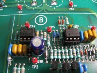
I think the 50R terminations I have are even rated at 2W so they could handle the 7Vrms+, but I think this KH4400B is set up to load down to 3.5Vrms with a matching 50R load. I'm curious about that test myself in terms of how well the AVC is working to keep the levels steady. I'm tempted to replace the TL074's in that section (the two chips in middle of the board in the section marked "B" in the photos) with TLE2074s, the "upgrade". 😀 Studied the TLE datasheet a bit through and they upgrade many things, but doesn't look like THD is one of them. Slightly less if I'm reading that right. But for the AVC circuit, especially this one using the analog multiplier, all the other stuff (than THD) probably is most important, just as long as the THD is only slightly less.
1audio - definitely, will do. I'm curious about those measurements too given the possiblity of swapping the regulators. I'm also curious just how bad the old 2200uF are. 🙂 I just got in and didn't get a chance to swap them out yet today. I'll measure the ripple under no-load and load going into the vregs with the old electros, then again with the new. I pondered upping those to 3300uf or 4700uf for the longest time (mouser has those in the same 16mm diameter 35V), but given those darn 2940/90 LDOs with their minimum *and maximum" load ESR table in the datasheet I figured best go for equivalent.
If anybody out there knows any reason why a LM2940CT-15/2990T-15 "LDO" (it really isn't) pair beats a on-seni MC7815/MC7915 pair, other than possibly 1V less dropout, please post! I'm just not seeing it from the datasheets.
Noise out of the regulators should be a great test for this new RTB2004 scope. 😀 The marketing literature is full of the statement "see small signal details in the presence of large signals (with the 10 bit ADC)". And my tests recent showed it triggering on around 184uV(rms) at 20Hz from the KH440B and 170uV(rms) or so at 1KHz from a Victor board with a resistive divider on the output.
Last edited:
Hey AGDR - if you have 50R termination, would you mind checking the output of your 4400B at 10Hz, 1kHz and 100kHz to see what you get in Vrms before clipping? Thanks.
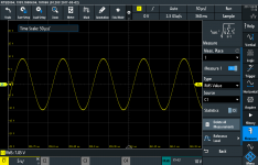
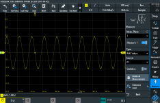
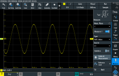
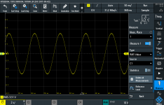
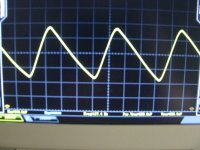
OK, here you go. 🙂 I did the tests with the 50R load, then removed it an ran again. The good news is the KH4400B's AVC circuit is amazing. It never clips. With the output voltage control all the way up the AVC limits every single frequency to between 3.44Vrms to 3.51Vrms. Maybe I won't mess with those TL072 chips after all!
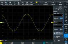
As expected with the terminator removed it goes up to 7Vrms. AVC works great here too, steady at 7 for all frequencies. The only time I saw it clip was when pressing the frequency multiplier buttons. For a second there would be clipping until the AVC restored the loop. Looks like the gain switches must be break-before-connect and the gain loop opens up during the press.
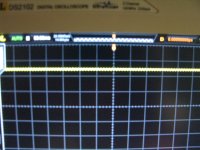
The bad news: the scope is dead! 😱 I've been having crashing problems with it ever since it arrived. They have become more frequent, crashed (screen freezes and the buttons don't respond) a couple of time during these tests. Somehow I didn't capture the screen for the 100KHz with-load test. The scope died before I could go back and get it. But I saw the reading, 3.5Vrms. I'll get the thing warranty swapped at Newark.
Photos:
* 5135 is the test setup. I tack soldered a pair of wires to the two PCB holes that feed the front panel 50R BNC jack, for the scope probe connection. 50R terminator installed.
* 17 is 10Hz with terminator, 3.51Vrms. The rms value is in the lower left of the screen on all of these.
* 18 is 100Hz with terminator, 3.44Vrms.
* 15 is 1K with terminator, 3.49Vrms.
* 16 is 10K with terminator, 3.49Vrms.
* 19 is 10Hz without terminator, 7.08Vrms.
* 20 is 100Hz without terminator, 7.09Vrms.
* 21 is 1KHz without terminator, 7.04Vrms.
* 22 is 10KHz without terminator, 7.05Vrms.
* 23 is 100KHz without terminator, 7.07Vrms.
Hoovering the mouse over these will show the photo number, clicking on arrows in the lower left will zoom it in..
1audio - I still have the Rigol scope here. I'll use that for the ripple tests.
Attachments
-
 IMG_5135.JPG722.9 KB · Views: 260
 -
 SCR23.PNG59.6 KB · Views: 141
 -
 SCR22.PNG61.1 KB · Views: 146
 -
 SCR21.PNG60.5 KB · Views: 127
 -
 SCR20.PNG60.1 KB · Views: 120
 -
 SCR19.PNG64.9 KB · Views: 133
 -
 SCR16.PNG62.5 KB · Views: 254
 -
 SCR15.PNG62.4 KB · Views: 248
 -
 SCR18.PNG57.4 KB · Views: 255
 -
 SCR17.PNG61.6 KB · Views: 273
Last edited:
Thats a drag with the scope. Let us and the EEV blog know about your warranty experience.
The output level accuracy is way beyond what your scope will show. In the cal they use a thermal converter (20 ppm or better accuracy on level vs. frequency) to check it. They are still the gold standard for accuracy for level response.
The KH stuff is really flat response. You will see a level transient when you change frequency, especially range. The AGC needs to adjust for the new frequency. If you watch test point 4 you will see the AGC correcting.
There is a 50 Ohm internal source Z so the 7V internal would be 3.5V across the 50 Ohm load. Load both outputs for max draw on the supplies. The schematic shows 24V DC on the raw supply so low dropout is not an issue. Peak current may be and that would explain changing regulators. As would a visit from a National sales guy in 1990.
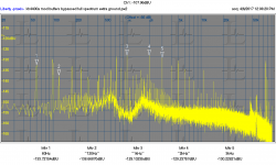
There is so much gain inside the feedback loop I doubt you will find many artifacts from the supply in there. Here is a plot of the full spectrum of the output with markers on the supply and H2 along with the fundamental feedthrough and H2 and H3 of the fundamental. Everything is -129 dB or less. I have found that a separate ground connection from the shell of the Quad output to the ground on the monitor out of the 725 gets rid of a lot of junk, the leakage I mentioned above.
The output level accuracy is way beyond what your scope will show. In the cal they use a thermal converter (20 ppm or better accuracy on level vs. frequency) to check it. They are still the gold standard for accuracy for level response.
The KH stuff is really flat response. You will see a level transient when you change frequency, especially range. The AGC needs to adjust for the new frequency. If you watch test point 4 you will see the AGC correcting.
There is a 50 Ohm internal source Z so the 7V internal would be 3.5V across the 50 Ohm load. Load both outputs for max draw on the supplies. The schematic shows 24V DC on the raw supply so low dropout is not an issue. Peak current may be and that would explain changing regulators. As would a visit from a National sales guy in 1990.
There is so much gain inside the feedback loop I doubt you will find many artifacts from the supply in there. Here is a plot of the full spectrum of the output with markers on the supply and H2 along with the fundamental feedthrough and H2 and H3 of the fundamental. Everything is -129 dB or less. I have found that a separate ground connection from the shell of the Quad output to the ground on the monitor out of the 725 gets rid of a lot of junk, the leakage I mentioned above.
Attachments
As the KH4402B is still in production, I wonder what they are thinking as they view this thread!
Thats a drag with the scope. Let us and the EEV blog know about your warranty experience.
I've been exchanging some PMs over there with Brian the R&S rep. about it. They are right on top of it. Pretty impressed so far. 🙂
As the KH4402B is still in production, I wonder what they are thinking as they view this thread!
Watch for some of 1audio's mods to show up in some future KH4402C. 😀
Also use your new scope to look at ripple no load vs max load.
Sent from my LG-H811 using Tapatalk
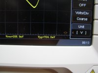
So here is the ripple under max load, the first 3 pictures. Unfortunately all with the Rigol. About 3/4 of a volt riding on top of 24V. I didn't even bother taking a picture of the ripple without a load given how small this is. This is the two electrolytics feeding the voltage regulators. Out of the voltage regulators the only ripple is about 10mV of the actual frequency the generator is set at, as expected. The load current through the regulator times the regulator output impedance.
The next photo - well I just couldn't resist trying the TLE2072ACPs in for the TL072BCPs in the AVC section. I socketed them and tried it. The TLEs don't work. The AVC reguation is all over the place and it doesn't work at all for 10Hz for some reason (one chip gets hot at that frequency so I assume it is oscillating there). So the old chips are back in and working great.
The final photos are changing out the power supply electrolytics. This made zero difference in the ripple. Exactly the same after as it was before, both input and output of the voltage regulator. Apparently those 20+ year old electros were still working pretty well. Note no leakage in the photo, but KH did a smart thing in mounting them upside down under the board. Any leakage wouldn't spread over the PC board and eat the traces. The new capacitors are 5mm shorter for the same capacitance and votlage. They fit under that fuse holder a lot better. KH had a nylon tie around the originals. I don't feel the need to do that with these shorter caps. In the last picture I have one of the old ones up for height comparison.
So this is 24V into the vregs and 15 out. And they used 2940/2990 LDOs? With a 9 volts of overhead? Why? Methinks the MC7815/MC7915 are going in.
And geezzzz - using the Rigol again after using the Rohde and Schwarz for a few days is like going from a Lamborghini to a tricycle. Everything is a struggle on the Rigol and the measured numbers, waveforms, and triggering are all over the place. I can hardly wait to get the R&S back!
Attachments


Last edited:
For the 4402B the improvement is easy. I just exchanged all IC with LT1468 except these two here. and added a variable control. This will put you at -135db (1KHz).

THx-RNMarsh
THx-RNMarsh
For the 4402B the improvement is easy. I just exchanged all IC with LT1468 except these two here. and added a variable control. This will put you at -135db (1KHz).
View attachment 610325
THx-RNMarsh
Here is data.... <-130dBv .... Of course to tune for lowest distortion, you have to be able to accurately measure it.
The added trim interacts with the other pot and makes adjustment a test of patience. It ended up at same value as factory. So no need to change anything except the IC's.
David's generator design is still 10dBv lower distortion and lower noise. An impressive achievement.

THx-RNMarsh
View attachment 610325
THx-RNMarsh
Here is data.... <-130dBv .... Of course to tune for lowest distortion, you have to be able to accurately measure it.
The added trim interacts with the other pot and makes adjustment a test of patience. It ended up at same value as factory. So no need to change anything except the IC's.
David's generator design is still 10dBv lower distortion and lower noise. An impressive achievement.
THx-RNMarsh
Last edited:
For the 4402B the improvement is easy. I just exchanged all IC with LT1468 except these two here. and added a variable control. This will put you at -135db (1KHz).
View attachment 610325
THx-RNMarsh
Here is data.... <-130dBv .... Of course to tune for lowest distortion, you have to be able to accurately measure it.
The added trim interacts with the other pot and makes adjustment a test of patience. It ended up at same value as factory. So no need to change anything except the IC's.
David's generator design is still 10dBv lower distortion and lower noise. An impressive achievement.
View attachment 610466
THx-RNMarsh
and with the cover on, computer on Battery power only and ON for 1 hr ---> 1.1KHz:

THx-RNMarsh
I loked again and I'm now convinced the harmonics are coming from the level detector. I looked at the signal on TP3 and its spectrum has the same harmonic pattern.
Simple fix would be a big filter cap but then the settling time gets really long.
I'm debating adding an inverter and ac coupling the inverted harmonic spectrum to cancel the one that is there and get clean DC. Its a long shot but I don't see any other easier way. Not sure its worth the effort if the residuals are all at -130 already.
I loked again and I'm now convinced the harmonics are coming from the level detector. I looked at the signal on TP3 and its spectrum has the same harmonic pattern.
I'm debating adding an inverter and ac coupling the inverted harmonic spectrum to cancel the one that is there and get clean DC. Its a long shot but I don't see any other easier way. Not sure its worth the effort if the residuals are all at -130 already.
Demian,
Try it... sounds interesting. filtering or cancellation. The cancellation is more interesting to me
-Richard
.
Old, thin, PC trace alert! TLE2072s work just fine for TL072s
A word of caution for anyone modifying these things: the PC traces are extremely thin in places and old, not well adhered to the board anymore.
When I removed U150 the tip that I used on the Hakko 808 vacuum desolderer was just a tad too big it turned out, 1.3mm vs. 1.0mm. and sucked two of the tiny PC pads right off the board. When I removed U165 I changed over to the 1.0 tips and that solved it, no missing pads, or so I thought.
I had repaired all the damage around U150 and thought everything was back together. But the x10 multiplier range wouldn't work at all and x1 was sluggish. After some time with a meter and magnifying glass this morning I found a hairline crack on the trace going from the pin 7 output of U165 to the feedback loop. Fixed it and all is back to normal.
The upshot: the TLE2072ACP chips do work just fine in place of the TL072BCPs! It even looks like the loop settles just a little faster with them in. The oscillation I was getting before (U165 back to 90F vs. 120F!) was due to that broken feedback loop.
KH4402B now on eBay
The fellow I bought my KH4400B from last week just let me know they have a KH4402B up for sale now, for $799:
Krohn Hite Model 4402B Ultra Pure Sinewave Oscillator | eBay
It also has the "make offer" button so maybe there is some negotiation room there. This is the currently-selling KH model of course. I think that I saw it listing for $1700 on the KH site but can't verify that right at the moment. The eBay listing claims it is functioning. My 4400B worked just fine.
Disclaimer: I'm not affiliated with this seller in any way, just a happy customer after my KH4400B purchase. I figured it would fit right in with the thread of modifying these things. 🙂
Last edited:
TI TINA model of the KH4400A osc/avc section
A few weeks ago 1audio had the good suggestion to whip up a Spice model for the KH4400A oscillator and avc sections in TI TINA. I've always used LT Spice until now, but I have to say I am mighty impressed with TINA. It has a huge number of built-in transistor and diodes models. Pretty much 80% of the semiconductor parts in these two sections in fact. I've added the OPA1642 model and used that part in place of the LM318N oscillator IC.
Unfortunately I haven't had time to wade through the frequency/multiplier switch network on the schematic yet to find a set of values for, say, 1KHz but everything else is there. All the unconnected lines on the left of the model go out to the switch network. A couple of the diodes are not the correct ones and would need to have models added. I've included the OPA1642 model in the archive here.
I wanted to go ahead and post this in case anybody out there wants to mess with it. 🙂 Might be helpful in testing out new chips, like that OPA1642, and in discovering the purpose of the "mystery" networks on the LM318N oscillator chip output.
Attachments
Last edited:
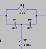
Here is a starting point for the R's and C'c based on the schematic and the simplified schematic-
For the C's use .032 uF (2 caps in series) and a 5.7K across the two caps and a 2.85K resistor to the junction of the two caps. I was not quite sure how to add them to your simulation.
For the C's use .032 uF (2 caps in series) and a 5.7K across the two caps and a 2.85K resistor to the junction of the two caps. I was not quite sure how to add them to your simulation.
Attachments
I was not quite sure how to add them to your simulation.
I'm not sure either! 🙂 I'll have to leave it for someone else out there to try simulating. Hey you were right about TI TINA, that is a great program. I rarely use Linear Tech chips but use TI chips all the time. Glad I learned how TINA works.
Another round of upgrades.
I mentioned raising the supply voltages with higher voltage regulators. I did it and tweaked R183 to get 10V RMS out. I wanted to see if this compromised the performance. It seems to have worked fine. From my junkbox I found this nice 5K Knobpot to replace the existing level control. The combination gives 3 digit resolution on the output voltage and 10V out which is really more useful. I have not found a problem with this yet but its only been about an hour. The THD+N 30KHz BW at 10V measures around -112 dB. The harmonics are all under -130 dB after tweaking the distortion trim. The response seems to hold at 5V to 100 KHz. There is a small level shift between bands I need to figure out (.05 dB it seems).
I mentioned raising the supply voltages with higher voltage regulators. I did it and tweaked R183 to get 10V RMS out. I wanted to see if this compromised the performance. It seems to have worked fine. From my junkbox I found this nice 5K Knobpot to replace the existing level control. The combination gives 3 digit resolution on the output voltage and 10V out which is really more useful. I have not found a problem with this yet but its only been about an hour. The THD+N 30KHz BW at 10V measures around -112 dB. The harmonics are all under -130 dB after tweaking the distortion trim. The response seems to hold at 5V to 100 KHz. There is a small level shift between bands I need to figure out (.05 dB it seems).
Attachments

Not yet. The pot is not quite accurate so I need to figure a better fix for that. I have stuff to deal with in front of this, but I have some headphone driver boards with LME49600 buffers I may use for output amps so I can drive 50 Ohms to 10V. Right now that's a major weakness in the unit. I would also like the balanced out of the 4402 but not worth the effort for all the mods necessary i think. The attenuator switch would need some involved rework.
Not yet. The pot is not quite accurate so I need to figure a better fix for that. I have stuff to deal with in front of this, but I have some headphone driver boards with LME49600 buffers I may use for output amps so I can drive 50 Ohms to 10V. Right now that's a major weakness in the unit. I would also like the balanced out of the 4402 but not worth the effort for all the mods necessary i think. The attenuator switch would need some involved rework.
I am sure you've seen the thread on the new and improved BUF634A
- Home
- Design & Build
- Equipment & Tools
- KH4400A upgrades