I had done some tweaks to my KH4400a some years ago. Recently several things, including getting a much better distortion analyzer got me back at working through the mods to confirm which are worthwhile and how clean it can get. Now is the time to document those changes. First I must thank AGDR for getting me to actually get this done.
The as shipped KH4400A (and closely related KH4402B) are quite good. Especially given it was designed in 1980 with the limitations of 1980 opamps.
The mod consists of replacing 5 opamps, and bypassing some excess internal circuitry. In 1980 your opamp choices for a project like this would be NE5532 or LM318 or very similar. A few ultra high performance opamps were available but expensive and hard to use.
The current generation of opamps form TI/National are a good fit for this task. They have the necessary drive and output swing with really linear internal circuitry and GBW to get extremely low distortion.
Keep in mind this is an instrument, not an audio product. I am focusing on changes that show lower distortion and noise on the output. No improvement, don't bother.
Short list-
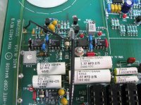
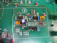
Replace U100, U103, U125, U183, U141 with sockets.
Install LME49710's into all except U125. Use an OPA 134 in that location.
Recalibrate and adjust distortion for minimum 2nd harmonic.
This will get to around -110 dB THD+N. Possibly further.
Going further bypassing the discrete 'helper" circuits seems to lower the distortion more. That entails removing (or just lifting one end) of the following resistors and adding jumpers:
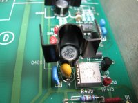
For the output amp U183 lift R186 and jumper from pin 6 of U183 to TP12.
Osc. Output amp U125 Lift R133, R126 and jumper U125 pin 6 to TP10.
For Inverter Amp R137, R138, R141 and jumper from U141 pin 6 to TP8.
Getting the distortion null really requires an SOTA analyzer or a passive twin-t + FFT. I'm getting approx -133 dB for all the harmonics at this stage. However at this level its easily possible that some cancellation is happening.
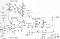
Schematic attached but not marked up with these changes.
The as shipped KH4400A (and closely related KH4402B) are quite good. Especially given it was designed in 1980 with the limitations of 1980 opamps.
The mod consists of replacing 5 opamps, and bypassing some excess internal circuitry. In 1980 your opamp choices for a project like this would be NE5532 or LM318 or very similar. A few ultra high performance opamps were available but expensive and hard to use.
The current generation of opamps form TI/National are a good fit for this task. They have the necessary drive and output swing with really linear internal circuitry and GBW to get extremely low distortion.
Keep in mind this is an instrument, not an audio product. I am focusing on changes that show lower distortion and noise on the output. No improvement, don't bother.
Short list-
Replace U100, U103, U125, U183, U141 with sockets.
Install LME49710's into all except U125. Use an OPA 134 in that location.
Recalibrate and adjust distortion for minimum 2nd harmonic.
This will get to around -110 dB THD+N. Possibly further.
Going further bypassing the discrete 'helper" circuits seems to lower the distortion more. That entails removing (or just lifting one end) of the following resistors and adding jumpers:
For the output amp U183 lift R186 and jumper from pin 6 of U183 to TP12.
Osc. Output amp U125 Lift R133, R126 and jumper U125 pin 6 to TP10.
For Inverter Amp R137, R138, R141 and jumper from U141 pin 6 to TP8.
Getting the distortion null really requires an SOTA analyzer or a passive twin-t + FFT. I'm getting approx -133 dB for all the harmonics at this stage. However at this level its easily possible that some cancellation is happening.
Schematic attached but not marked up with these changes.
Attachments
Thanks for sharing this valuable info.
And I literally just missed a chance to snag a cherry KH4400B!
BK
And I literally just missed a chance to snag a cherry KH4400B!
BK
I had done some tweaks to my KH4400a some years ago. Recently several things, including getting a much better distortion analyzer got me back at working through the mods to confirm which are worthwhile and how clean it can get. Now is the time to document those changes. First I must thank AGDR for getting me to actually get this done.
The as shipped KH4400A (and closely related KH4402B) are quite good. Especially given it was designed in 1980 with the limitations of 1980 opamps.
The mod consists of replacing 5 opamps, and bypassing some excess internal circuitry. In 1980 your opamp choices for a project like this would be NE5532 or LM318 or very similar. A few ultra high performance opamps were available but expensive and hard to use.
The current generation of opamps form TI/National are a good fit for this task. They have the necessary drive and output swing with really linear internal circuitry and GBW to get extremely low distortion.
Keep in mind this is an instrument, not an audio product. I am focusing on changes that show lower distortion and noise on the output. No improvement, don't bother.
Short list-
Replace U100, U103, U125, U183, U141 with sockets.
Install LME49710's into all except U125. Use an OPA 134 in that location.
Recalibrate and adjust distortion for minimum 2nd harmonic.
This will get to around -110 dB THD+N. Possibly further.
Going further bypassing the discrete 'helper" circuits seems to lower the distortion more. That entails removing (or just lifting one end) of the following resistors and adding jumpers:
For the output amp U183 lift R186 and jumper from pin 6 of U183 to TP12.
Osc. Output amp U125 Lift R133, R126 and jumper U125 pin 6 to TP10.
For Inverter Amp R137, R138, R141 and jumper from U141 pin 6 to TP8.
Getting the distortion null really requires an SOTA analyzer or a passive twin-t + FFT. I'm getting approx -133 dB for all the harmonics at this stage. However at this level its easily possible that some cancellation is happening.
Schematic attached but not marked up with these changes.
Thank you, Demian! I am in!
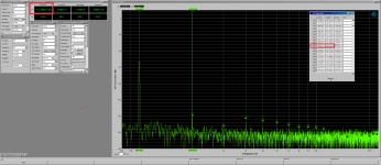
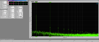
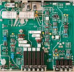
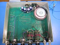
Attached pictures are an FFT of my unmodified 4400A showing its THD at almost -116dBV THD with H2 at -120dBV, as well as the THD+N at almost -108dB at 2Vrms. Also attached is a high resolution top view of the 4400A PCB.
After clicking on the pictures ot open them, be sure to click on the lower left corner expansion arrow to see the original size for these pictures, they are LARGE.
Ordering parts now.
Attachments
Last edited:
Very similar to mine except you have a heat sink on Q138 mine never had. Also mine was a beater when i got it, making the mods/tweaks and tests seem less of an issue.
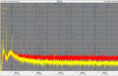
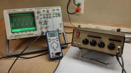
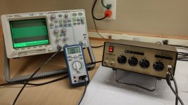
Here is a plot showing the modified KH4400 (Red) vs a Victor oscillator (Yellow) at the monitor output of the 725. H2 is at about -133 dB on both- probably a limit in the 725. Victor's oscillator does not have the higher harmonics.
They both measure below -110 dB THD+N. Victors measures approx -118 dB and KH4400 approc -114 dB all depending on who knows what interference.
I would do the opamp mods without the other changes first to get a good baseline. The other changes are more involved and may not contribute.
I'll upload a picture of the poor abused beast but the ones I have are too big for now.
Attachments
Going further bypassing the discrete 'helper" circuits seems to lower the distortion more. That entails removing (or just lifting one end) of the following resistors and adding jumpers:
For the output amp U183 lift R186 and jumper from pin 6 of U183 to TP12.
Osc. Output amp U125 Lift R133, R126 and jumper U125 pin 6 to TP10.
For Inverter Amp R137, R138, R141 and jumper from U141 pin 6 to TP8.
Based on your "Going further" comments above, these additional steps are marked in the attached PDF. Would you please clarify and confirm my correct understanding of the following:
1. By lifting and adding jumpers back in, the 6 resistors are gone but their corresponding circuit connections are still maintained.
2. By using jumpers from the 3 opamps directly to the TP's, the opamp outputs are paralleling and not replacing the output of the drive transistors.
Thanks.
Attachments
Lifting the resistors shuts off the transistors so the jumpers connect the opamps directly. I did this to test the changes should I need to reverse them. I'm trying to not overstress the PCB with rework. I'm still not sure the discrete circuits add or subtract from the performance. The rework with the lifted resistors is the least obtrusive way to test the changes.
Your markups are correct.
Your markups are correct.
Last edited:
Lifting the resistors shuts off the transistors so the jumpers connect the opamps directly. I did this to test the changes should I need to reverse them. I'm trying to not overstress the PCB with rework. I'm still not sure the discrete circuits add or subtract from the performance. The rework with the lifted resistors is the least obtrusive way to test the changes.
Got it - lifting and NOT replacing with jumpers to turn off the transistors make sense, therefore jumpering opamp outputs to the TPs completes the picture. I was confused when I read in your first post "...That entails removing (or just lifting one end) of the following resistors and adding jumpers." I guess you meant the jumpers from opamps to the TPs, not jumpers in place of the resistors. The Voutmax for the LME49710 is ±12.5 into 600R so there is lots o' juice.
The residual distortion in the output was a bit of a puzzle. I think I know the source however- The AGC circuit. There is feedback to linearize the JFET gain control element and there is a DC voltage for setting its gain. I just looked at the FET drive and the feedback is there with about 3 mV of fundamental on it. However it has a trail of harmonics similar to what's on the main output at about 35 dB below the fundamental.
AGC circuits are always difficult. They are a compromise between high gain and accuracy (exceptional flatness in this case) fast settling, stability (too much gain and it will have overshoot and constant shifting) and feedthrough of the samples audio signal. it this case I think the rectified and filtered signal is coming through the AGC and modulating the FET. That won't be an easy fix.
AGC circuits are always difficult. They are a compromise between high gain and accuracy (exceptional flatness in this case) fast settling, stability (too much gain and it will have overshoot and constant shifting) and feedthrough of the samples audio signal. it this case I think the rectified and filtered signal is coming through the AGC and modulating the FET. That won't be an easy fix.
I think the rectified and filtered signal is coming through the AGC and modulating the FET. That won't be an easy fix.
On the list of todo's - if the THD/THD+N figures do drop sufficiently - is a revamp of the power supply.
The 4400A and 4402B power supply section vary in 2 notable areas - the use of LM2940/2990 vs MC7815/7915 and the near tripling of capacitance in C200/C201 to 2200µF from 800µF before the voltage regulators and the dramatic increase of C202/C203 from 6.8µF to 2200µF after them. It may be for additional power needs of a balanced configuration, but the line fuse rating increase from 0.1A to only 0.25A does not reflect a huge increase in demand.
The only explanation that remains is additional ripple reduction. This mod has to wait for all others to succeed first so it is down the road and we shall see then.
Last edited:
The 4400B and 4402B can drive 50 ohms at full out times 2. The 4400A is barely good for 2v into 50 Ohms so less power needed. The schematic says the raw DC is 27 volts so ripple is not a big issue. I don't see ripple or hum to speak of in the output. Grounding a leakage currents across chassis are the bigger issue.
Sent from my LG-H811 using Tapatalk
Sent from my LG-H811 using Tapatalk
This should be fun to mod. I have a 4400B and a 4402B. I was gong to sell the 4400 but now I will try your mods.
One problem area for the well worn models like the older 4400 is the switch contacts are worn and may not always make good contact. They should all be cleaned as best you can... the atten button array can just be ordered and replaced if really bad/intermittant.
THx-RNMarsh
One problem area for the well worn models like the older 4400 is the switch contacts are worn and may not always make good contact. They should all be cleaned as best you can... the atten button array can just be ordered and replaced if really bad/intermittant.
THx-RNMarsh
Last edited:
The 4400B and 4402B can drive 50 ohms at full out times 2. The 4400A is barely good for 2v into 50 Ohms so less power needed. The schematic says the raw DC is 27 volts so ripple is not a big issue. I don't see ripple or hum to speak of in the output. Grounding a leakage currents across chassis are the bigger issue.
Sent from my LG-H811 using Tapatalk
There is plenty of room to explore in 2 areas: the power supply and EMI/grounding.
The rectified 27VDC is from noisy 1N4002's and filtered by only one cap, not a CRC or LC, and the 7815/7915 are also pretty ancient regulators with probably 0.2mV noise going into a cap of just 6.8µF before it goes to the opamps. None of this is good power supply hygiene anymore and should cost relatively little to tidy up.
Both the grounding scheme and implementation is also open some improvement as well. The topology is good enough to meet a 0.0005% THD spec but we are looking for way more. Perhaps taking away from "utilitarian" and closer to "anal" will get back a few dB's. That will definitely help stem leakage currents.
Thank you, Demian! I am in!
Attached pictures are an FFT of my unmodified 4400A showing its THD at almost -116dBV THD with H2 at -120dBV, as well as the THD+N at almost -108dB at 2Vrms. Also attached is a high resolution top view of the 4400A PCB.
After clicking on the pictures ot open them, be sure to click on the lower left corner expansion arrow to see the original size for these pictures, they are LARGE.
Ordering parts now.
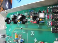
Can you mark on the pcb picture which IC are the ones to remove and replace? My pcb has no ic markings.
THx-RNMarsh
Can you mark on the pcb picture which IC are the ones to remove and replace? My pcb has no ic markings.
THx-RNMarsh
Attached are both the opamps marked as well as parts number layout on the PCB.
Attachments
The KH4402B vs. KH4400B vs. KH4400A, for the modding
Hey RNMarsh, yeah i wound up with a KH4400B from eBay. I was just grabbing something quick that could do a 20Hz 200uV test on a new scope.
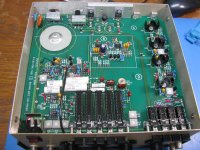
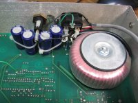
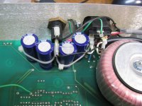
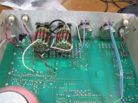
Pictures of the outside and inside of the KH4400B below, it is a different animal from the KH4400A, but some of the circuits appear to be the same and mod-able. I've found relatively little information on the net about the KH4400B vs. the KH4400A, so here is a rundown for folks Googling in the future.
A ***huge*** thanks here to 1audio for providing the manuals with schematics and information so I could figure out what this thing was.
Appears that the KH4400B has nearly the same - and possibly *exactly* the same - PC board as the current-model KH4402B. I tested and there is an inverted main out PC hole (different from the regular inverted out, this has heat-sinked drivers transistors like the main out), so it could produce a differential signal, just isn't being used.
Some other differences between the KH4402B, KH4400B and KH4400A:
* The 4400B, like the current 4402B, uses LM2940CT/LM2990T regulators vs. the LM7818/7819 in the "A". They are heat sinked to the back panel vs. board foil in the "A". But... I never have liked the 2940/90 pair over the years. Not *really* LDO, the fine print says 2V across still needed to maintain regulation and they have the typical LDO low esr warning on output C. I'm probably going to swap back to the MC7815/MC7815. The on-semi MC78xx/MC79xx parts may be less noisy per the data sheet than the NJM or the LM, at least that is the case with the +/-12Vregs used in the O2 headamp. Something to look into.
* The KH4400B, like the current KH4402B, uses heat-sinked NPN/PNP (2N2219A & 2N2905A) metal can driver transistors good for 3W with heat-sink (datashetet) and powered in 2 identical sections by NE55534s. The "A" uses TO-92 plastic transistors, as I recall, for the drivers.
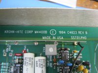
* The KH4400B appears to have the same LM318N and LM310 parts for the quad out section, so there is one where mods will apply to all units.
* The KH4400B use those same 2200uf 35V radial main filter caps that the KH4402B uses, vs. the two 800uV for the "A". Lol, the board date is 1994, those 23 year old "2000 hour" electros are getting changed later tonight, although not leaking yet. 🙂 FWIW those were Nichicon Vx(M) in my unit, which has become the 5mm shorter UVR. The Mouser # is 647-UVR1V222MHD. Interesting that the manual lists a 2200uF 35V Sprague part that is no longer made.
* The KH4400B uses the AD633 analog multiplier chip in the AVC that the KH4400A does, vs. the FETs in the "A".
* The KH4400B and KH4402B uses toroids for the power transformer vs. the E-I for the "A".
No snubber on the power transformer secondary in any of these KH. I wonder if there is ringing getting into the circuitry anywhere. A Hagerman snubber would be an easy add.
Clicking on the arrows in the lower left of the photo will expand it. More photos posted below, I ran out of photo slots.
This should be fun to mod. I have a 4400B and a 4402B. I was gong to sell the 4400 but now I will try your mods.
THx-RNMarsh
Hey RNMarsh, yeah i wound up with a KH4400B from eBay. I was just grabbing something quick that could do a 20Hz 200uV test on a new scope.
Pictures of the outside and inside of the KH4400B below, it is a different animal from the KH4400A, but some of the circuits appear to be the same and mod-able. I've found relatively little information on the net about the KH4400B vs. the KH4400A, so here is a rundown for folks Googling in the future.
A ***huge*** thanks here to 1audio for providing the manuals with schematics and information so I could figure out what this thing was.
Appears that the KH4400B has nearly the same - and possibly *exactly* the same - PC board as the current-model KH4402B. I tested and there is an inverted main out PC hole (different from the regular inverted out, this has heat-sinked drivers transistors like the main out), so it could produce a differential signal, just isn't being used.
Some other differences between the KH4402B, KH4400B and KH4400A:
* The 4400B, like the current 4402B, uses LM2940CT/LM2990T regulators vs. the LM7818/7819 in the "A". They are heat sinked to the back panel vs. board foil in the "A". But... I never have liked the 2940/90 pair over the years. Not *really* LDO, the fine print says 2V across still needed to maintain regulation and they have the typical LDO low esr warning on output C. I'm probably going to swap back to the MC7815/MC7815. The on-semi MC78xx/MC79xx parts may be less noisy per the data sheet than the NJM or the LM, at least that is the case with the +/-12Vregs used in the O2 headamp. Something to look into.
* The KH4400B, like the current KH4402B, uses heat-sinked NPN/PNP (2N2219A & 2N2905A) metal can driver transistors good for 3W with heat-sink (datashetet) and powered in 2 identical sections by NE55534s. The "A" uses TO-92 plastic transistors, as I recall, for the drivers.
* The KH4400B appears to have the same LM318N and LM310 parts for the quad out section, so there is one where mods will apply to all units.
* The KH4400B use those same 2200uf 35V radial main filter caps that the KH4402B uses, vs. the two 800uV for the "A". Lol, the board date is 1994, those 23 year old "2000 hour" electros are getting changed later tonight, although not leaking yet. 🙂 FWIW those were Nichicon Vx(M) in my unit, which has become the 5mm shorter UVR. The Mouser # is 647-UVR1V222MHD. Interesting that the manual lists a 2200uF 35V Sprague part that is no longer made.
* The KH4400B uses the AD633 analog multiplier chip in the AVC that the KH4400A does, vs. the FETs in the "A".
* The KH4400B and KH4402B uses toroids for the power transformer vs. the E-I for the "A".
No snubber on the power transformer secondary in any of these KH. I wonder if there is ringing getting into the circuitry anywhere. A Hagerman snubber would be an easy add.
Clicking on the arrows in the lower left of the photo will expand it. More photos posted below, I ran out of photo slots.
Attachments
-
 IMG_5088.JPG727.4 KB · Views: 143
 -
 IMG_5087.JPG767 KB · Views: 178
 -
 IMG_5086.JPG542.9 KB · Views: 139
 -
 IMG_5085.JPG669.6 KB · Views: 138
 -
 IMG_5084.JPG601.6 KB · Views: 158
 -
 IMG_5083.JPG784.9 KB · Views: 248
 -
 kh4.jpg182.9 KB · Views: 229
 -
 kh3.jpg207.6 KB · Views: 214
 -
 kh2.jpg204.9 KB · Views: 224
 -
 kh1.jpg185.3 KB · Views: 223
Last edited:
... the atten button array can just be ordered and replaced if really bad/intermittant.
Well, need one; to order from KH directly ?
BR
Gary
Hey RNMarsh, yeah i wound up with a KH4400B from eBay. I was just grabbing something quick that could do a 20Hz 200uV test on a new scope.
Pictures of the outside and inside of the KH4400B below, it is a different animal from the KH4400A, but some of the circuits appear to be the same and mod-able. I've found relatively little information on the net about the KH4400B vs. the KH4400A, so here is a rundown for folks Googling in the future.
A ***huge*** thanks here to 1audio for providing the manuals with schematics and information so I could figure out what this thing was.
Appears that the KH4400B has nearly the same - and possibly *exactly* the same - PC board as the current-model KH4402B. I tested and there is an inverted main out PC hole (different from the regular inverted out, this has heat-sinked drivers transistors like the main out), so it could produce a differential signal, just isn't being used.
Some other differences between the KH4402B, KH4400B and KH4400A:
* The 4400B, like the current 4402B, uses LM2940CT/LM2990T regulators vs. the LM7818/7819 in the "A". They are heat sinked tot he back panel vs. board foil in the "A". But... I never have liked the 2940/90 pair over the years. Not *really* LDO, the fine print says 2V across still needed to maintain regulation and they have the typical LDO low esr warning on output C. I'm probably going to swap back to the MC7815/MC7815. Note at Mouser the LM7815/LM7915 are 300uV of noise, the NJM7818/19 are 200uV and the MCs are 100u/V. That came up way back when with the O2 headamp, the on-semi fixed regs are quieter.
* The KH4400B, like the current KH4402B, uses heat-sinked NPN/PNP (2N2219A & 2N2905A) metal can driver transistors good for 3W with heat-sink (datashetet) and powered in 2 identical sections by NE55534s. The "A" uses TO-92 plastic transistors, as I recall, for the drivers.
* The KH4400B appears to have the same LM318N and LM310 parts for the quad out section, so there is one where mods will apply to all units.
* The KH4400B use those same 2200uf 35V radial main filter caps that the KH4402B uses, vs. the two 800uV for the "A". Lol, the board date is 1994, those 23 year old "2000 hour" electros are getting changed later tonight, although not leaking yet. 🙂 FWIW those were Nichicon Vx(M) in my unit, which has become the 5mm shorter UVR. The Mouser # is 647-UVR1V222MHD. Interesting that the manual lists a 2200uF 35V Sprague part that is no longer made.
* The KH4400B uses the AD633 analog multiplier chip in the AVC that the KH4400A does, vs. the FETs in the "A".
* The KH4400B and KH4402B uses toroids for the power transformer vs. the E-I for the "A".
Thanks for the very nice pictures, AGDR! A superb catch indeed.
...more KH4400B internal photos
I ran out of photo slots. Here are the rest of the KH4400B internal photos....
Clicking on the arrows in the lower left of the photo will expand it.
I ran out of photo slots. Here are the rest of the KH4400B internal photos....
Clicking on the arrows in the lower left of the photo will expand it.
Attachments
* The KH4400B, like the current KH4402B, uses heat-sinked NPN/PNP (2N2219A & 2N2905A) metal can driver transistors good for 3W with heat-sink (datashetet) and powered in 2 identical sections by NE55534s. The "A" uses TO-92 plastic transistors, as I recall, for the drivers.
Hey AGDR - if you have 50R termination, would you mind checking the output of your 4400B at 10Hz, 1kHz and 100kHz to see what you get in Vrms before clipping? Thanks.
- Home
- Design & Build
- Equipment & Tools
- KH4400A upgrades