Cap banks are these, 1 per channel:
Capacitor Filter Bare PCB, Support 100pcs D12.5mm Electrolytic Capacitors. | eBay
I can highly recommend these.
I bought 500pcs of 1000uF BC caps from Germany for a reasonable price.
10pcs of 50000uF caps would be more expensive and have higher ESR.
Thanks!
Capacitor Filter Bare PCB, Support 100pcs D12.5mm Electrolytic Capacitors. | eBay
I can highly recommend these.
I bought 500pcs of 1000uF BC caps from Germany for a reasonable price.
10pcs of 50000uF caps would be more expensive and have higher ESR.
Thanks!
Big capacitors are great too you get hundreds soldering points less.
Few big caps is easy to bypass with polypro mkp's or pio.
Anyway electronic hobby is interesting 🙂
Few big caps is easy to bypass with polypro mkp's or pio.
Anyway electronic hobby is interesting 🙂
jlithen, do you have a link you can post on the Chinese made enclosure you have used. I would like to have a look at these, thanks.
Regards. Gary.
Regards. Gary.
Putting aside Jlithen's spectacular build - what kind of power supply capacitance are people going with? I have 2 x 20,000 80V caps I can use (one for each amp module), but perhaps I need more....?
To comment on a few posts.
Yes big caps need less solder points, but probably it does not matter if one fails either 🙂
One thing I particularly like about these PCBs is that they are compact and rectangular. In my Aleph Monster I have them standing upright to save space.
Back to the VFET, I do not think it is particularly picky about the PSU?
Or is front end sensitive? I think my miniminimal hum is from my not yet perfect wiring.
Here is a link to the amp I've used the enclosure from:
a100Linear
I would guess they will not sell the enclosure separately.
My friend once dealt with them regarding buying one complete channel.
They wanted 600€ + shipping, not including any taxes, for 2 PCBs.
If you want Calaf parts PM me.
I have scrapped 3 of them for parts. You will find part of the story in another thread here 🙂
Putting aside Jlithen's spectacular build - what kind of power supply capacitance are people going with? I have 2 x 20,000 80V caps I can use (one for each amp module), but perhaps I need more....?
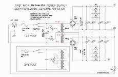
Mr. Pass psu schematic show 4x 15000 uF = 60000 uF for one channel.
Smaller capacitor value first after rectifier bridge,
the biger ones install after resistors in case if you have two different capacitors values for this build.
Have a nice day 🙂
Attachments
Edit for precision :
Smaller capacitor value first after rectifier bridge and 2.2K resistor
the biger ones install after 0.47R resistors in case if you have two different capacitors values.
Smaller capacitor value first after rectifier bridge and 2.2K resistor
the biger ones install after 0.47R resistors in case if you have two different capacitors values.
Hi Folks,
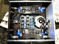
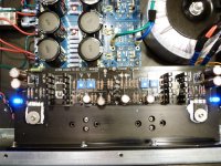
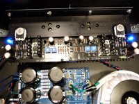
I'm finally nearing the last hurtle on my build but I think that I may have an issue with offset. I ran through the resistor checks in accordance to Nelson's instructions, no problems everything checked out fine. Then I went to the next step to check the voltages, everything also checked out fine. I moved on to bias up the front end and was able to set P1 and P2 to match the VGS of the transistors, in my case the 2SJ28 was marked 117, so adjusted to get 12.7v across T16 to gnd. 2SK82 was marked 97 so adjusted P2 to -10.7. I was able to get 1.5v across R5 and R6 and everything was stable for about 1 1/2 hrs. But the offset between P18 and gnd on the right channel was 1 v and on the left channel was -3.3 v, so I'm thinking something must be amiss. All parts are from the DIY audio kits. Here are a few pics of my build. Case is 400 mm 4U, trafo is Antek 400VA, psu is DIY audio. I'd appreciate any thoughts.
Thanks
Paul
Attachments
Resistors positions are ok particulary 220 R and 2.2K ?
No wire connections for input and speakers ?
No wire connections for input and speakers ?
Yes, adjustment is needed. P18 is allowed some offset, but all 4 pots
need to be tweaked in rotation in half-way steps (or less) to converge on
the proper bias and minimal offsets at P18 and the output.
need to be tweaked in rotation in half-way steps (or less) to converge on
the proper bias and minimal offsets at P18 and the output.
Ah, Thanks Nelson, I read things as only P3 and P4 needing to be tweaked in rotation. I'll go back to square one and try sneaking up on it again monitoring all four points.
Paul
Paul
Do we need the output snubber for the store power supply board? It is not shown in this schematic :
http://origin.dastatic.com/forums/gallery/data/500/VfetPSU.png
http://origin.dastatic.com/forums/gallery/data/500/VfetPSU.png
Last edited:
No. Leave the output snubber empty.
Do we need the output snubber for the store power supply board?
Yes, adjustment is needed. P18 is allowed some offset, but all 4 pots
need to be tweaked in rotation in half-way steps (or less) to converge on
the proper bias and minimal offsets at P18 and the output.
Just to clarify for everyone you have previously said +-200mV is no problem at T18.
Success ! After being put back on the right path I was finally able to bias up the front end and hit 70 MV offset ( t18-gnd). Very twitchy pots, it might have been a bit easier with 25 turn pots instead of the single turn ones though, but now the job is done. Hopefully I'll find time this weekend to install the VFETs and finalize things. I'll go dig out some cheap speakers for the maiden voyage.
Paul
Paul
Mr. Pass psu schematic show 4x 15000 uF = 60000 uF for one channel.
Smaller capacitor value first after rectifier bridge,
the biger ones install after resistors in case if you have two different capacitors values for this build.
Have a nice day 🙂
Do you think these would be ok?
http://au.mouser.com/ProductDetail/...Q1uosSi9M7vwsbcYtHmqDh/JqXIhhEIp1FjYMB70fGQ==
- Home
- Amplifiers
- Pass Labs
- Sony vFET Amplifier Part 2