Amp works 🙂
Well, since I was not successful even I knew, the V-Fet was right, I wanted to finish another project first to gain confidence. And I did 🙂 - Salas DCG3 preamp.
Today I was looking for a cold joint in the Fet part and I found it at the HEXFet. Was hard to see, but good to measure.
And now, the amp is warming up. I am really happy about that. Need some more patience for the adjustment.
Have a nice Sunday 🙂
I am really happy about that. Need some more patience for the adjustment.
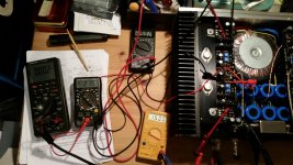
get youself at least 3 Multimeters! one for Vfet (R32) bias, one for Frontend offset and one for speakers offset. I found the Voltagedrop of about 1,5V over ..was it R6?...the most UN-critical value, not having the habit of running away.
Frontend offset still wandering between +-70mV in mine. Nevertheless sounds very good. Maybe termal coupling of the jfets would help.
good luck!
Hi Noelectrix, thanks! I do have 3 DMMs and have adjusted my first channel 2 weeks ago or so. I just have to adjust the second one which I was not getting to work before. After having finished the Salas pre today is a good day and next week a good week to give it a first listening session. 🙂
Just for the record, while I have about 8 multimeters on my bench, I
routinely adjust with just one....
routinely adjust with just one....
... says Nelson Pass
...
he's little cat to my Papa
Papa is adjusting them with mind


Or solder wires to pcb test points and 4 positions switch and you can do it with one multimeter 🙂
if possible - use make-before-brake switch** , and induce plenty of VFet smoke

**majority of them are exactly that
**majority of them are exactly that
You can build open " input & output " box with quality switch inside and
the same color pairs of wires with crocodile clamps for easy visualisation of your tests points.
With 8 position switch you have equivalent of 8 multimeters with only one.
Yeah take care make slowly little value changes steps 🙂
the same color pairs of wires with crocodile clamps for easy visualisation of your tests points.
With 8 position switch you have equivalent of 8 multimeters with only one.
Yeah take care make slowly little value changes steps 🙂
Attachments

When I had the amp up and running (and at temperature) I redid the frontend and output stage bias on the live amp, using four DMM's. It was fun watching the pots interact and slowly and iteratively approaching the minimum offset operating point.
The audio quality of this Sony VFET diy amp still amazes me every single day.
The audio quality of this Sony VFET diy amp still amazes me every single day.
Attachments
These single turn Bourns may be more stable keeping the adjusted values than the multiturn. But the way to this stable point was really looong. At least for me. They suck a little bit in this very special application. But it worked after some short one and a half hours. 😰
Rodeodave,
When you implemented the TL431 shunt regulators for the front end cascode circuitry from VFET pt2 article onto the diy audio VFET board, did you purposely omit the R24 (332 ohm) resistor? Did you implement R29 and R30 the cascode feedback resistors (each 10k)?
Thank you, your build is awesome
Best,
Anand.
Last edited:
Whoops! My bad. I noticed that R4 on the diyVFET board is exactly that...332 ohms! What about cascode feedback? Bad idea?
Best,
Anand.
Best,
Anand.
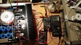
Another success story 🙂 Quiet when supposed to and singing beautiful when supposed to. Thanks to Nelson for making it possible and a special thank you to Rodeodave who spotted the initial error placement of Q5 and Q6.

looks great, such a brilliant generous gift, look, it´s even labeled as Firstwatt, not Pass DIY 🙂
i still have no case and it´s just playing on cheap speakers in my studio. fast, amazing soundstage and so on.....
i still have no case and it´s just playing on cheap speakers in my studio. fast, amazing soundstage and so on.....
After setting the bias and offset, and amp is running fine, is it worth the effort to jump a wire across the 0R1 resistor, R32, and then touch up offset? The wire can be cut later if bias needs to be reset for some reason.
- Home
- Amplifiers
- Pass Labs
- Sony vFET Amplifier Part 2