Audioromy 838A
Hi
Do You have powersupply scematic for the 838A model with 845 tubes?
Best regards
Jens Posselt
here the schematic of the fu29 power supply
Hi
Do You have powersupply scematic for the 838A model with 845 tubes?
Best regards
Jens Posselt
FU29
Hi Guys,
Dear Sir. I am from Australia.I have a similar problem.Burnt out Power supply Board and burnt out Driver board. I need to build new Boards. (The people I bought from wont answer my emails) If you have a layout of the Driver board PCB. with component layout It will help. Power supply board I can work it out.Thxing you Hope you can Help me. Await a email from you. Peter email. peter.gay@gmail.com
I am from Singapore and I really need help and advice on my fried audioromy Fu29 amp. The amp just got fried on its own last week.
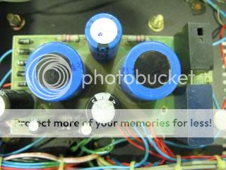
And upon opening up the bottom plate, I saw 2 pieces of badly burned resistors.
Due to the resistors burned condition, I can't figure out the resistors value to get them replace. I really appreciate if some kind souls, having the same amp could open up the bottom casing and advice on the resistors color code and value, could help me out on this mess.
All help is greatly appreciated.


FU29 amp purchased from Prime Amp
Hello I purchased one of these amps from seller Prime Amp on ebay and now I'm having second thoughts. For one thing the seller promised to ship after two days from payment and one week later still nothing. The seller seems very selective in responding to email and ebay messages, and after reading about all the negatives and complaints wrt to unreliability of the amp, I'm wondering about canceling the order. However I did see one earlier post from a member who came up with some good mods to improve reliability. Is there a modified schematic or illustrated guide as to what to replace/add and where? I am pretty good with electronics noting that my experience is with solid state not "tooobes". Any assistance in improving the amp or suggestions to scuttle this project altogether will be most appreciated...! I really don;t need a $438 door stop.
Hello I purchased one of these amps from seller Prime Amp on ebay and now I'm having second thoughts. For one thing the seller promised to ship after two days from payment and one week later still nothing. The seller seems very selective in responding to email and ebay messages, and after reading about all the negatives and complaints wrt to unreliability of the amp, I'm wondering about canceling the order. However I did see one earlier post from a member who came up with some good mods to improve reliability. Is there a modified schematic or illustrated guide as to what to replace/add and where? I am pretty good with electronics noting that my experience is with solid state not "tooobes". Any assistance in improving the amp or suggestions to scuttle this project altogether will be most appreciated...! I really don;t need a $438 door stop.
mods
It looks like one end of the 5 watt 270ohm is connected to a 470k resistor to one of the valve pins and then a 220K ohm in series with a 1.2 (meg ohm?) resistor to another valve pin / bridged over to one of the biasing pots? Also which version board is this? thanks for any info!
Hi, that amp can be problematic.....so what did i do with it?
1. i lowered the G2 voltage to just slightly lower than 200volts..
2. discarded the fixed biasing and used cathode biasing instead....
3. i used a cathode resistor of 250 ohms 5 watts bypassed with 220ufd/100 volt ecap..
4. replaced plate caps with ceramic types....
5. i added 2.2k carbon comp grid stoppers on the output tubes...
after that the amp amp behaved very well....the owner was happy....😉
It looks like one end of the 5 watt 270ohm is connected to a 470k resistor to one of the valve pins and then a 220K ohm in series with a 1.2 (meg ohm?) resistor to another valve pin / bridged over to one of the biasing pots? Also which version board is this? thanks for any info!
Ebay should be willing to work with you and cancel it. If anything link to this thread and mention that you feel the design is a safety hazard. No one wants to take a $500 risk on a lawsuit. Best of luck.
Well the dealer says he has shipped the amp already, so I'll have to take a chance on it. I am intrigued by the mods done shown in photos in an earlier post, but of course I can't work to photos. If possible it would be great to see a schematic highlighting the mods? Anyone? thank you
Hi AJT, I saw 270ohm 5 Watts resistor from your pic. Please advise. Thank you.
yes, i converted this amp from fixed bias to cathode resistor bias,
the 270 ohms was chosen to limit plate dissipation to around 15 watts per plate......
there are two ways to do this, one is the cathode resistor bias, and the other
is to lower the g2 voltage, one or both can be used for fine tuning....
so i added a grid stopper, 1k to 4.7k can be used, and grid leaks can be 220k to 390k ohms,
i do not have a complete schematic, i never needed one,
It looks like one end of the 5 watt 270ohm is connected to a 470k resistor to one of the valve pins and then a 220K ohm in series with a 1.2 (meg ohm?) resistor to another valve pin / bridged over to one of the biasing pots? Also which version board is this? thanks for any info!
the thing to remember is that, cathode resistor bias should limit plate dissipation to around 15 watts per plate,
then from fixed bias to cathode resistor bias means grid leak returns to ground.
g2 voltage can be lowered by voltage deviders to a little bit below 200 volts...
I received the Audioromy FU29 and it operates but does red plate on one FU29 (829B) valve.
I've checked the amp bias as attached photo shows and the diagram is incorrect, point 1C is 500VDC and cannot be adjusted to .5V
The other test points indicated appear to be correct. Since red plating is a serious issue I'm considering returning the amp back to Hong Kong --- unless anyone has ideas on how to bias correctly... ? thanks
I've checked the amp bias as attached photo shows and the diagram is incorrect, point 1C is 500VDC and cannot be adjusted to .5V
An externally hosted image should be here but it was not working when we last tested it.
The other test points indicated appear to be correct. Since red plating is a serious issue I'm considering returning the amp back to Hong Kong --- unless anyone has ideas on how to bias correctly... ? thanks
i got about ten of them made by Cetron, you have to select one that does not red plate,
your other option is the 5894....
your other option is the 5894....
Yes correct, when I swap the tube the red plate follows the swap, so the tube is definitely the culprit, thank you. It seems like a nice amp but as always the expense in valve gear is always greater than anticipated.
By the way the voltage shown of 500V is that what you reduced to 300V AJT?
https://postimg.org/image/o67rb6lgd/
By the way the voltage shown of 500V is that what you reduced to 300V AJT?
https://postimg.org/image/o67rb6lgd/
I received the Audioromy FU29 and it operates but does red plate on one FU29 (829B) valve.
I've checked the amp bias as attached photo shows and the diagram is incorrect, point 1C is 500VDC and cannot be adjusted to .5V
<snip>
I can't see the point clearly as the picture is far too small. The plate current in each half of the 829s in mine can be measured across a 10 ohm resistor in series with the respective plate lead. You would measure across the resistor. The currents in both plate current sampling resistors should match. (One pot is balance and one is bias) There are a number of variations. Mine is a year old and was built after they went back to the Williamson configuration.
There have been many recent tales of bad surplus 829s so if you are contemplating replacement be very careful.
The link in the post just above s/b full size. So sorry I am a newbie at this... what wattage 10 ohm resistor do you use? 1 watt? Or larger? Another interesting point is that the pots seem to be "fixed" with some sort of glue, so cannot be adjusted.
Valves listed on ebay.... I don't have any way to test other than stick them in the amp 🙂
3E29 JAN 829B GE Single New Old Stock Electron Tube Broadcast HAM Radio | eBay
Considering those (seller f/back not good however)
TIA
3E29 JAN 829B GE Single New Old Stock Electron Tube Broadcast HAM Radio | eBay
Considering those (seller f/back not good however)
TIA
So at 40 ma and 500V the wattage of the 10 ohm resistor should be at least 25watts? That would be quite a large resistor! This is my first foray into valves, I usually do solid state amps. Much safer!
10 ohm 1 watt, at 20mA this is 200mV very low watts...
the 829b is a two tube in one envelop device so matching between them is a hit and miss thing, that is why we see red plating in one side, if both sides redplate, then your biasing is a problem..
the way to balance plate currents is to be able to adjust negative grid bias individually...while monitoring plate currents...
that is why, i think that the 5894 will fit this amp better since the 5894 has a single cathode and g1's on opposite sides, symmetrical constructions gives better matching than the 829b
By the way the voltage shown of 500V is that what you reduced to 300V AJT?
the amp used a full wave bridge to generate 500 volts, this is above the 450 volt rating of the filter caps.....not safe in the long run...
for sweep tubes and transmitting tubes like these, i use a fill wave doubler so that deriving the G2 supply is easily derived,
200 volts is the g2 rating of this tube...
Pic of red plating in link
Well I'm reading two things. One post says the balance can be adjusted and the other says it's a matter of swapping tubes to find one that works and won't red plate. Regardless, the bias/balance adjustment pots have been super glued into a fixed state so I've initiated a return with Prime Amp and hopefully that at least will go okay! Pic of red plating in link, regards
https://postimg.org/image/rnk0dhmxb/
The link in the post just above s/b full size. So sorry I am a newbie at this... what wattage 10 ohm resistor do you use? 1 watt? Or larger? Another interesting point is that the pots seem to be "fixed" with some sort of glue, so cannot be adjusted.
In my amp the resistors are already there on the edge of the PCB at the spot you point to. (Note depending on when built 1 ohm resistors could be in there.) You measure across the existing resistor using the range appropriate for the resistor used. (200mV for 1 ohm, and 2V for 10 ohm) These resistors are there so that the factory can set the quiescent operating current and balance the tubes; they probably use 2 meters simultaneously to do it.
The "glue" is used to lock the pots in place, it's not normally very strong and should not prevent you from adjusting the pots when needed.
Why not post the picture directly here? If you like I can add the picture in your link to that post.
- Home
- Amplifiers
- Tubes / Valves
- Help!!! My Audioromy FU29 amplifier was fried!