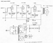
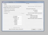
I'm learning LTSpice in order to determine if it's possible to make a stereo Fi Primer 6SN7-->300B with the Magnequest TFA-204 OPT using parts I already have.
The original schematic and a screenshot of the current state of my LTSpice simulation are attached.
Here are the parts I'm trying to work with.
Mike LaFevre told me that the 60mA rating on the TFA-204 is conservative, and that I should feel comfortable going up to the 350V/60mA combo.
I was able to lower the values of R2 from 62K to 55K and R4 from 27K to 13.5K to get fairly close to the original plate voltages for the 6SN7 (70V for the lower and 210V for the upper).
Where I'm running into trouble is figuring out how to model the output transformer to simulate the correct B+ and current through the 300B and the OPT.
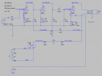
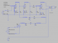
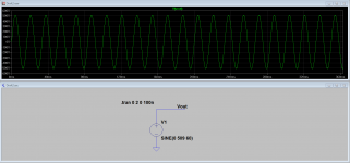
Since the original schematic uses an 800V center tapped HV into a 5U4-GB, I tried to model it using the 720V winding into the GZ34 by connecting two 360V (1/2 of 720V) DC voltage sources via a ground connection (see image) to get positive and negative legs. I know it's AC coming out of my real PT, but I couldn't figure out how to model AC voltage for that.
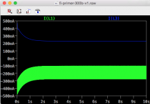
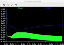
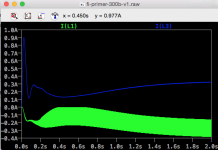
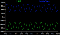
That results in 264.1V at the plate of the 300B with way too much current going through the power supply choke and the OPTs (see attached graph) -- but without any impedance set on the OPT model.
The primary inductance of the TFA-204 is 10H, and Mike told me that the turns ratio of the primary to the 8ohm secondary is 18.26 to 1. According to an LTSpice video tutorial, you model the shared inductance across the tranformer by creating separate inductors for primary and secondary, and connecting them via a K statement, which I've done. You need to set the inductance values to reflect the square of the turns ratio. Rounding down to 18, the square is 324, so the primary and secondary H values (L1 and L2 in the schematic) are set to 324H and 1H.
However, I've set no series resistance value on the OPT primary, because if I enter 3K there, the B+ becomes way too low.
At this point I'm not really sure what to ask other than, What am I doing wrong here?
Thanks for any help you might be able to provide.
PS -- I also couldn't figure out how to model the hum pot on the 5V filament of the 300B, so I left it out and simply used a 5VDC voltage source.
The original schematic and a screenshot of the current state of my LTSpice simulation are attached.
Here are the parts I'm trying to work with.
- TFA-204 -- 3K primary, 60mA
- PT -- HV windings are 660V and 720V CT, also has 6.3V and 5V
- Triad C14-X choke (200mA, 150 ohm)
- GZ34 rectifier
- 350V plate, 60mA, -74V grid into 3K for about 8w output
- 300V plate, 50mA, -63V grid into 3K for about 6w output
- 250V plate, 40mA, -52V grid into 3K for about 4w output
Mike LaFevre told me that the 60mA rating on the TFA-204 is conservative, and that I should feel comfortable going up to the 350V/60mA combo.
I was able to lower the values of R2 from 62K to 55K and R4 from 27K to 13.5K to get fairly close to the original plate voltages for the 6SN7 (70V for the lower and 210V for the upper).
Where I'm running into trouble is figuring out how to model the output transformer to simulate the correct B+ and current through the 300B and the OPT.
Since the original schematic uses an 800V center tapped HV into a 5U4-GB, I tried to model it using the 720V winding into the GZ34 by connecting two 360V (1/2 of 720V) DC voltage sources via a ground connection (see image) to get positive and negative legs. I know it's AC coming out of my real PT, but I couldn't figure out how to model AC voltage for that.
That results in 264.1V at the plate of the 300B with way too much current going through the power supply choke and the OPTs (see attached graph) -- but without any impedance set on the OPT model.
The primary inductance of the TFA-204 is 10H, and Mike told me that the turns ratio of the primary to the 8ohm secondary is 18.26 to 1. According to an LTSpice video tutorial, you model the shared inductance across the tranformer by creating separate inductors for primary and secondary, and connecting them via a K statement, which I've done. You need to set the inductance values to reflect the square of the turns ratio. Rounding down to 18, the square is 324, so the primary and secondary H values (L1 and L2 in the schematic) are set to 324H and 1H.
However, I've set no series resistance value on the OPT primary, because if I enter 3K there, the B+ becomes way too low.
At this point I'm not really sure what to ask other than, What am I doing wrong here?
Thanks for any help you might be able to provide.
PS -- I also couldn't figure out how to model the hum pot on the 5V filament of the 300B, so I left it out and simply used a 5VDC voltage source.
Attachments
Last edited:
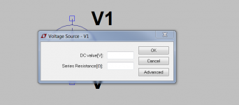
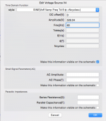
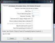
Open the generator dialog and click advanced. Select Sine and enter voltage and frequency. You can ignore small signal values for this experiment. See attachments below. Note that the value shown is Vpk so multiply your target value by 1.414 to convert Vrms to Vpk.
As an aside the reverse biased side of the 5AR4 never conducts since the generator is set to DC. (The side connected to the -360V source) Just change both to sine source as shown and it will work.
As an aside the reverse biased side of the 5AR4 never conducts since the generator is set to DC. (The side connected to the -360V source) Just change both to sine source as shown and it will work.
Attachments
Thanks, kevinkr. 360 * 1.414 = 509.04. I entered that in amplitude plus the 60Hz frequency and got very different graph behavior as well as voltages in the microvolts.
Attachments
What model are you using for the 5AR4? The fact that you are measuring OV on the generator output means there is a problem with generator configuration - thought you were using transient simulation? V6 should not be there.
Also you could build a power transformer using coupled inductors (K1 L1 L2... 1.0) You can including the winding resistance and get something a little closer to real world ignoring any core related effects.
Also you could build a power transformer using coupled inductors (K1 L1 L2... 1.0) You can including the winding resistance and get something a little closer to real world ignoring any core related effects.
Note that I am using the older version of LTSpice and you are using the newer version. I have the newer version installed on my home machine, here at work not the case (yet) - despite the difference in dialogs, the settings and directives should return the same values shown.
I'm on a Mac, which makes the interface even more different, though the dialogue for entering .tran settings is the same as yours. I created a simple voltage source like the one you just posted and got the same graph as you.
I ran the sim on the circuit with the updated .tran setting and got slightly high plate current on the choke and way negative current through the OPT (graph attached). Voltage on the B+ rail is about 55uV.
I'll fiddle with the PT some more and will see if I can mock up a model of that with inductors.
Right now I'm wondering how to make a good model of the OPT, though, since the circuit doesn't account for its impedance or resistance.
Attachments
Last edited:
There's an error in your schematic which might matter. Look at the 5 volt filament connections.
All good fortune,
Chris
All good fortune,
Chris
> learning LTSpice
Really over-complicating.
> how to model the hum pot
With a perfect 300B (and SPICE models are always perfect), the pot would just be centered. Which makes it two resistors.
BUT the tube-model you are using is NOT a 2-lead filament, it is a generic one-lead-cathode. It does not model the 2 legs and (pot or winding) CT, because you know how to do that and it does not impact the simulation.
Forget hum-pot. (Until you build!)
> 660V and 720V CT
You can't simulate a AC-to-DC rectifier with DC sources. You can scratch-out approximations in the dirt (a hand calculator helps).
720V AC CT is 360V each side. With cap-input you approach 1.414 times this, or 509V, awful high, even with vacuum rectifier loss. With choke-input the average is 0.9 or about 324V. Looks good, but vacuum-rectifier losses will put you way low of usual 300B voltages.
660V AC CT is 330V each side. Cap-input you approach, 466V, still high. Choke-input about 297V, low.
NOTE that 330VAC leads to 466V DC no-load (before the 300B heats and sucks), which means lower-cost "450V" e-caps will work OK.
It seems likely you will need to add resistance to drop B+ into a good zone.
To know the rectifier and resistance losses we have to know how much the 300B tube will suck (the little tubes hardly count). We do NOT need to simulate the whole 300B+OT+Rk, we can derive an equivalent resistance.
> 350V plate, 60mA, -74V grid
> 300V plate, 50mA, -63V grid
> 250V plate, 40mA, -52V grid
Is the "350V" with or without the cathode bias resistor drop?? (Your sim is wrong here.) You really want 424V-302V.
350V plate, 60mA, -74V grid = 424V, 424V/60mA= 7,067 Ohms
300V plate, 50mA, -63V grid = 363V, 363V/50mA= 7,260 Ohms
250V plate, 40mA, -52V grid = 302V, 302V/40mA= 7,550 Ohms
All about seven, seven-and-a-half, K Ohms.
So for a dirt-sketch, we can scratch "7,100 Ohms equivalent load on power supply" and get reasonable answers, more exact for the higher-stress cases.
> resistance value on the OPT primary, because if I enter 3K there, the B+ becomes way too low.
3K is the audio impedance. The DC resistance is ideally ZERO. This will serve for dirt-sketching. In practice we "know" a good winding will have DCR about 5%-10% of audio impedance. So tell the sim "250 Ohms", a mid-high guess. (Or measure it?) This causes like 250r*0.060A or 15V of drop. Nearly insignificant in a 400V amplifier. Negligible unless you must pass a strict "Power Output Specification". As you are suggesting outputs from 4W to 8W, you are not this fussy.
Forget OT DCR.
The attached PSUD sim gives 416V DC which slots just-under your 8W case. Lower DCV with bigger R1 (1K gets near the 6W case). It has under 10 milliVolts ripple. This is about 0.2mV at speaker (3dB PSRR in 300B, 30:1 in OT) which makes ripple around 83dB below 1W, or 12dB SPL in 95dB/W speaker. Peaks on first-cap touch 440V DC, so use good "450V" caps.
Attachments
The primary inductance of the TFA-204 is 10H, and Mike told me that the turns ratio of the primary to the 8ohm secondary is 18.26 to 1. <snip> so the primary and secondary H values (L1 and L2 in the schematic) are set to 324H and 1H.
Why the large discrepancy between the stated primary inductance and the ones used for the model? Hardly realistic, is it?
PRR: Wow, thank you for explaining all that. I definitely understand this better now, especially the effective load impedance.
So, given your 7.1Kohm hypothetical load impedance, I installed Wine on my Mac and ran a couple of sims in PSUD2. For the hell of it, I tried using a 5Y3-G full-wave rectifier, without a dropping resistor as you used for a GZ34, to see how the current and voltage shook out (sim screenshots attached).
360V -- 402V & 56mA at R1
330V -- 367V & 52mA at R1
Am I correct in thinking that, assuming the sim is accurate, the plate of the 300B would see 402V and 367V in these two versions? In other words, can I take these to be the operating points of the 300B, pending build, actual measurement, and adjustment?
jazbo8: I got those numbers by adhering to the guidelines of the company that makes LT spice, which say to square the turns ratio for use in the model. If that's what the model needs, I guess it doesn't square the values for you after you enter them. I'll try it with the actual values to see what happens.
Attachments
I'll try it with the actual values to see what happens.
If Lp = 10H, then Ls = 10/18.26^2 ~ 0.03H.
There's an error in your schematic which might matter. Look at the 5 volt filament connections.
Chris, are you saying I don't need to add the 5V filament supply to the model? Should I just remove the 5V source and keep the 880R resistor?
Is the 880R resistor the cathode bias resistor?
As I pointed in an early post you need to remove V6. (5V source) The filament is modeled as a simple cathode connection, you should have only the 880 ohm resistor and cathode bypass capacitor.
Thanks, Kevin. Sorry I missed that.
I removed the 5V source and am experimenting with different values for R9 to get the current on the OPT within the 60mA range. Right now it's at 4.5K, with 300V on the plate, and the wave form is not looking good at all.
I removed the 5V source and am experimenting with different values for R9 to get the current on the OPT within the 60mA range. Right now it's at 4.5K, with 300V on the plate, and the wave form is not looking good at all.
I've done a little more digging and discovered that that the dc resistance of the TFA-204 primary is 140 ohm. Just wanted to put that up here since it came up before.
Source is this page:
Re: tfa204 - mqracing - MagneQuest/Peerless Forum
Source is this page:
Re: tfa204 - mqracing - MagneQuest/Peerless Forum
> assuming the sim is accurate
It can only be as accurate as the numbers you feed it. The "31r" in the PT is a wild dart throw. The "2r" in the caps is probably wrong but not enough to matter.
We also know that PSUD can get off-track for very unusual values, but this is spot-on what it was designed to do.
You are showing 360V-400V. Your target points including cathode resistor are 300V-425V. I think you will end up near the higher-power conditions without tweak. Maybe not 8W, but well over 4W output. I would have no fear for the 300B at the expected dissipation. You are FAR below the 36W Pdiss rating and the 100mA cathode current, and your running plate-cathode voltage will be below 400V.
Last edited:
Thanks, PRR. Please excuse another newbie question, but would running plate-cathode voltage = plate minus cathode voltage or plate plus cathode voltage?
jazbo8: thank you so much for showing me how to calculate the inductance ratio for the OPT. The numbers are much better now that the proper figures are in the sim.
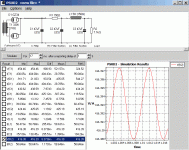
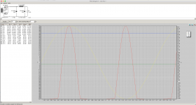
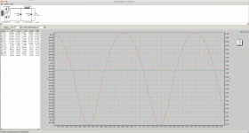
So, I've been trying to figure out whether the OPT current ratings are given by manufacturers as peak values or as some kind of average or RMS. This is partly because I've been having trouble getting a working model for the Fi Primer 300B without clipping. The voltage source at the audio input had been set to 0.25V @ 1000Hz, so I changed it to 0V @ 0Hz to see what happens. Instead of sine waves through the OPT, we now get flat lines.
So, then I decided to adjust the B+ voltage and cathode resistor values to get the idle plate voltage and current of the 300B to 300V @ 50mA, which works with a B+ value of 307V (attached).
I also adjusted R6 (27K --> 6.6K) and R4 (27K --> 20.5K) to keep the originally spec'd plate voltages on the two halves of the 6SN7 at 70V and 210V respectively.
With no signal going through the circuit, we get flat lines at the target values of 300V @ 50mA (attached).
If I introduce a 0.1V @ 1000Hz signal, the current sine waves in the OPT go from -30mA to -73.5mA peak-to-peak (attached).
The -73.5mA would exceed the 60mA rating of the TFA-204.
Would that cause core saturation, even though the idle current is at 50mA?
Attachments


- Status
- Not open for further replies.
- Home
- Amplifiers
- Tubes / Valves
- Modeling Fi Primer 300B with LTSpice