Note that the 60mA current rating is the static DC rating of the transformer and does not include the AC signal component, so as long as you are in the ball park of 60mA quiescent current you should be fine.
Note that the simulation will not ever get the operating point absolutely right, it will however get you close enough to be representative in most cases.
Note that the simulation will not ever get the operating point absolutely right, it will however get you close enough to be representative in most cases.
I suggest building it up (in the simulator) stage by stage. Start with the output stage. Get it biased right and working well. Move to the driver stage. Etc. A "big bang" test just tells you "doesn't work" (as you've discovered). A systematic test will tell you "doesn't work" but also make it possible to figure out why it doesn't work.
Right now your 300B runs at 250 Vak, which is pretty meagre. Most run 360 V. I prefer 400 V.
Tom
Right now your 300B runs at 250 Vak, which is pretty meagre. Most run 360 V. I prefer 400 V.
Tom
I'm in the 400VAK camp for 300B as well, but 350V is acceptable, much below this and what is the point really?
OK, so from what you're saying, I gather that Vak = Va - Vk, correct?
If so, then taking PRR's PSUD voltage of 416V, using my existing components, if I set the B+ to 416V, then there's 407.6V on the plate of the 300B. To get an idle current of 60mA, I then have to set the cathode resistor to 1.2K, which results in a cathode voltage of 71.1V.
Vak = 407.6 - 71.1 = 336.5V
If that's correct, it's still a bit low for your preferred range.
Changing the B+ supply to 435V results in 426.6V on the plate. Nudging the cathode resistor to 1.25K to maintain a 60mA idle current leaves a cathode voltage of 74.9:
426.6 - 74.9 = 351.7Vak
... which is just inside Kevin's "acceptable" range.
To get 400Vak, I have to do something like 498V B+ and up the cathode resistor to 1.5K for 60mA, resulting in:
489.75Va - 88.3Vk = 401.45Vak
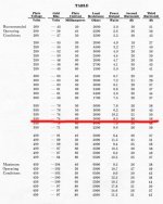
If these are correct, then I'm confused about what the plate voltage rating on a tube datasheet means. As per my original post, the WE datasheet recommends the following combination for a 60mA idle current into a 3K load (attached):
350V plate, 60mA, -74V grid into 3K for about 8w output
Does it mean 350 volts anode-to-cathode (as opposed to anode-to-ground)?
If so, then the 351.7Vak combo listed above is pretty close to the op point line underlined in red in the attached datasheet image.
If so, then taking PRR's PSUD voltage of 416V, using my existing components, if I set the B+ to 416V, then there's 407.6V on the plate of the 300B. To get an idle current of 60mA, I then have to set the cathode resistor to 1.2K, which results in a cathode voltage of 71.1V.
Vak = 407.6 - 71.1 = 336.5V
If that's correct, it's still a bit low for your preferred range.
Changing the B+ supply to 435V results in 426.6V on the plate. Nudging the cathode resistor to 1.25K to maintain a 60mA idle current leaves a cathode voltage of 74.9:
426.6 - 74.9 = 351.7Vak
... which is just inside Kevin's "acceptable" range.
To get 400Vak, I have to do something like 498V B+ and up the cathode resistor to 1.5K for 60mA, resulting in:
489.75Va - 88.3Vk = 401.45Vak
If these are correct, then I'm confused about what the plate voltage rating on a tube datasheet means. As per my original post, the WE datasheet recommends the following combination for a 60mA idle current into a 3K load (attached):
350V plate, 60mA, -74V grid into 3K for about 8w output
Does it mean 350 volts anode-to-cathode (as opposed to anode-to-ground)?
If so, then the 351.7Vak combo listed above is pretty close to the op point line underlined in red in the attached datasheet image.
Attachments
> Does it mean 350 volts anode-to-cathode
On these sheets, yes. On the test bench, a 0-100V variable bias supply is much more convenient than a big hot variable cathode resistor. "Most" tube data is given this way.
But living with non-cheap tubes, use cathode bias whenever possible! (I think this is in RDH.) It really protects the tube. On high-Mu tubes it is not much waste heat. Yes, on the low-Mu 300B it is considerable heat. But I would not run "fixed" bias on costly tubes unless the amp had a current meter, so I knew when it was out-of-sorts.
Thanks. You'd think a datasheet that means 350V anode-to-cathode would say 350V anode-to-cathode, but I guess the writers assumed audience knowledge when compiling it.
Now I finally understand your post from the bottom of p.1. Sorry it took so long to grasp, and thank you again.
I've done two kit builds, and this is my first foray into tinkering with schematics.
Now I finally understand your post from the bottom of p.1. Sorry it took so long to grasp, and thank you again.
I've done two kit builds, and this is my first foray into tinkering with schematics.
Note that WE (who was supporting talking-movie houses who disliked failures) gives 450V with 97V bias, total 547V, as an allowed condition. While the 80mA is high for the OT you have, it will NOT burn-up, not even suck at 133% rated current. May shave 3 semi-tones of deepest bass at a given exact THD. You could run the amp this way for many days, and certainly long enough to take measurements and ponder alternatives.
BUT---
If we collect all the WE published data for 300B at 3K load, there is a bump.
From theory and observation, we know a tube stage optimized for one supply voltage will work very well over a wide range of supplies without value changes. As the B+ drops to half, we might increase Rk 20%-40%, but the trend is smooth.
The WE data for 400V(pk) is different from the rest. Ip is shown lower for 400V than for 350V. The implied Rk is way larger, and the harmonic figures are 5+dB worse. I think the tech mis-guessed the optimum.
In the attached image, the pink line is OP's original pick; the odd 400V is the next line down.
I believe the optimum Rk for a 3K loading can be 1.22K over the range 350V-450Vpk (424V-547V of B+). At 400Vpk this suggests 70mA with 85V bias.
Attachments

OK, so from what you're saying, I gather that Vak = Va - Vk, correct?
Yes.
If so, then taking PRR's PSUD voltage of 416V, using my existing components, if I set the B+ to 416V, then there's 407.6V on the plate of the 300B. To get an idle current of 60mA, I then have to set the cathode resistor to 1.2K, which results in a cathode voltage of 71.1V.
Vak = 407.6 - 71.1 = 336.5V
Your sim sheet in Post #19 shows 300 V on the anode and 50 V on the cathode of the 300B. That's Vak = 300-50=250 V.
If these are correct, then I'm confused about what the plate voltage rating on a tube datasheet means. As per my original post, the WE datasheet recommends the following combination for a 60mA idle current into a 3K load (attached):
350V plate, 60mA, -74V grid into 3K for about 8w output
Does it mean 350 volts anode-to-cathode (as opposed to anode-to-ground)?
350 V plate, -74 V grid should tip you off that the cathode is at ground. That gives Vak = 350 V and Vgk = -74 V. You can achieve the same results by lifting the cathode and plate by 74 V and grounding the grid. Note that the data sheet specifies two limits for the 300B depending on the biasing scheme used (cathode vs fixed bias).
Before you get too far in blowing up your expensive tubes and transformers, I suggest flipping through Morgan Jones, "Valve Amplifiers" (ISBN: 978-0080966403). It's a very worthwhile read and it will answer many of your questions, as well as generate some new and very relevant questions. 🙂
Even if you don't want to blow money on books (hey, it only costs about half of what a "budget" 300B tube costs) you can request it at your local library.
I commend you for simulating the circuit first. Awesome! Reading Jones' book is the logical next step and it'll help you gain confidence in your design process more so than any forum thread can.
Tom
Last edited:
You're definitely getting it now, and I will also second Tom's recommendation for Morgan Jones "Valve Amplifiers 4th Edition." It's well worth the money. I have 3 of the 4 editions as well as both editions of his "Building Valve Amplifiers."
Thanks, guys. I have copies of both Morgan Jones books, and though I started Valve Amplifiers last year, much of it didn't sink in because I don't have a mathematical mind. I decided to start playing with circuit sims in order to visualize what he was talking about, and your feedback has finally enabled me to grasp the rudiments of setting up tubes so that I can *start* reading Jones. Luckily, we got this out of the way at the beginning of spring break so I can actually immerse in it.
I'm going to order the OPTs so I can take measurements, and will report back once I've got something breadboarded.
I'm going to order the OPTs so I can take measurements, and will report back once I've got something breadboarded.
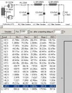
OK, I can't stop simming because it's too fascinating. Curious about power supply for the 350Vak slot discussed above, which needs a 435V B+ supply. Going with PRR's figure for R(pk eff) of 5.8K (post #27), and adding 1.25K for the cathode resistor and 140R for the OPT primary's DCR, we get an effective load of 7.19K for the B+.
Using my existing PT, choke, and GZ34 rectifier in PSUD2, rounding to a 7.2K load resistor, the closest result comes with the 360V winding and a 157R dropping resistor before the pi filter (attached).
The voltages and current are as predicted in the LTSpice model, which is really cool (attached).
However, Diff is now 39.4 mA, which I gather from PRR's discussion in post #9 is the ripple measurement. His example with 416V supply in post #9 showed ~8mA Diff. If 39.4 mA Diff will be noisy, then maybe I should aim for lower operating points.
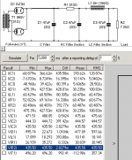
Playing around again to keep the PT but try different chokes, I created a double pi filter with two Hammond 159S (4H, 225mA, 65R) and increased the dropping resistor to 170R, resulting in the required voltage and current on R2 but about 3mA Diff -- MUCH lower (attached).
I'll play around with this some more and will then turn to Morgan (promise) to see what he has to say about it.
Using my existing PT, choke, and GZ34 rectifier in PSUD2, rounding to a 7.2K load resistor, the closest result comes with the 360V winding and a 157R dropping resistor before the pi filter (attached).
The voltages and current are as predicted in the LTSpice model, which is really cool (attached).
However, Diff is now 39.4 mA, which I gather from PRR's discussion in post #9 is the ripple measurement. His example with 416V supply in post #9 showed ~8mA Diff. If 39.4 mA Diff will be noisy, then maybe I should aim for lower operating points.
Playing around again to keep the PT but try different chokes, I created a double pi filter with two Hammond 159S (4H, 225mA, 65R) and increased the dropping resistor to 170R, resulting in the required voltage and current on R2 but about 3mA Diff -- MUCH lower (attached).
I'll play around with this some more and will then turn to Morgan (promise) to see what he has to say about it.
Attachments

Duh, forgot filter cap before dropping resistor. With that added in and values adjusted to work with my existing equipment, Diff looks even better at below 3mA, for the 350Vak operating slot.
Attachments
Last edited:
> Diff is now 39.4 mA
PSUD is weak on Kirchoff's Law.
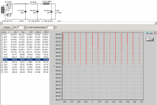
I prefer to look at V. V(C(last)) looks like 37mV down to 3mV. Estimating peak plate swing as 200V, and about 2/3rd of B+ buzz dropped across OT, max audio is 60,000 times bigger than hum or 95dB down from max output. Taking 95dB SPL/Watt speaker effectiveness, and say 6 Watts or 103dB SPL max, buzz is at 8dB SPL which is very low. Lower to the ear because of poor ear sensitivity at 120Hz. Because there are two stages filtering after the first cap, we expect higher harmonics to be very low. (Is the not-shown wave-form sine-like or jagged/spikey?)
PSUD is weak on Kirchoff's Law.
I prefer to look at V. V(C(last)) looks like 37mV down to 3mV. Estimating peak plate swing as 200V, and about 2/3rd of B+ buzz dropped across OT, max audio is 60,000 times bigger than hum or 95dB down from max output. Taking 95dB SPL/Watt speaker effectiveness, and say 6 Watts or 103dB SPL max, buzz is at 8dB SPL which is very low. Lower to the ear because of poor ear sensitivity at 120Hz. Because there are two stages filtering after the first cap, we expect higher harmonics to be very low. (Is the not-shown wave-form sine-like or jagged/spikey?)
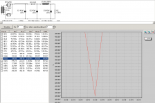
Attached is a graph showing a closeup of the wave at C3 (the last capacitor), which looks spiky more than sine-like to me. Edit: Added an even closer-up screenshot that reveals a pointy waveform.
My speakers are 91.5db efficient.
Thanks for going through your explanation of calculating hum. I'm not sure I completely follow, but I'm reading Morgan Jones, which is easier to grasp now, and will be getting to the PSRR section soon.
My speakers are 91.5db efficient.
Thanks for going through your explanation of calculating hum. I'm not sure I completely follow, but I'm reading Morgan Jones, which is easier to grasp now, and will be getting to the PSRR section soon.
Attachments
Last edited:
300 power supply
your transformer current rating is not enough, that's why there is a lot of voltage drop
your transformer current rating is not enough, that's why there is a lot of voltage drop
I've been doing some more simming and have a question about PSUD2. On everyone's advice above, I've been modeling the power supply load of the 300B at the 350Vak operating point, represented in the model as a single resistor that incorporates OPT DCR + Rp + Rk for a value of roughly 7.2K.
But under Kirchoff's law, doesn't the rest of the amplifier (the 6SN7s, their plate load and cathode resistors, the voltage dropping resistors, etc.) put a load on the HV power supply as well? Should I be adding those values to the resistor at the end of the chain in PSUD2?
I ask because I'm trying to determine whether I can use my current PT, which has an HV secondary of 720V/200mA, or if I really need to purchase a more conventional 800V PT.
Modeling the 300B only, it's easy to get a 436V B+ supply from the 720V tap, but I'd hate to overload something and ruin it when it powers the entire circuit.
PSUD is good software, but not quite optimal to test AC behaviour (LTSpice is better).
For rough estimate try to use instead of resistive load a stepped load.
Typical 300B -one channel- static B+ load about 70mA (300B), plus 15-30mA (first and second stage driver).
First stage driver current is -almost- constant (for example 10mA), the second "eats" 10-20mA -depending of signal modulation-. If you simulate this as stepped load, the step is from 20mA to 40mA.
The 300B current stepped from 0 to 140mA (70mA +/- 70mA).
So the overall step is from 20mA to 180mA.
euro21: thanks for the suggestion of the stepped load suggestion. I'm going to fiddle around with it tonight.
OK, I think I figured out that the reason my current 300B is only getting about 380V B+ is that there's not enough current headroom in the HV tap so it was causing the voltage to sag. I ended up buying a Hammond 378CX which can handle 530mA on the 800V winding.
About cathode resistors for the 300B, I see that most schematics spec 20W resistors, which seems like overkill. If I run at the WE operating point of 350Vak/60mA into a 5K load, a 1.5K cathode resistor seeing 60mA would dissipate 5.4W (0.06^2 * 1500 = 5.4). Wouldn't a 10W resistor be just fine?
Last edited:
Wouldn't a 10W resistor be just fine?
The rule of thumb is four times multiplication.
If you have aluminium housed, chassis mount power resistor AND satisfactory (large) dissipation surface (for example Vishay RH010 required 129 sq. in. surface area with free air ventillation) -bottom panel isn't the better choice-, 10W would be adequate.
- Status
- Not open for further replies.
- Home
- Amplifiers
- Tubes / Valves
- Modeling Fi Primer 300B with LTSpice