I don't have that luxury as I'm indoors in a small room. That's why I use damping panels at critical reflection points to absorb. And mix in diffused queues of a bigger space with my virtually created Haas Kickers. Then add a hint of reverberation (digitally and random) to hide my real room. Making you feel being in a larger space.
The Haas Kicker helps create depth and more 3D like imaging. The hint of reverb is hardly noticeable... I don't hear it coming from the back.
I tried to use real space IR's but that get's old fast. You get the same room in every recording. It was fun at first but irritated me pretty fast. The random solution works better and isn't noticeable, until you turn it off. The less I need the better.
What can I say, I like it. Makes my room feel bigger.
Short story: Corner line arrays can save space, can eliminate ceiling and front wall reflections, and can be fairly efficient. Using 24 Vifa TC9s, a 3.5" full range driver, a corner floor to ceiling line array was created. The array measures and sounds pretty awesome and achieves the design goals.
Long story: If you read Toole and other research, it says that the reflections that color the sound the most are the ceiling and front wall (the wall behind speakers). Reflections from side walls can add a sense of spaciousness but reflections from the ceiling and floor are perceived as modifying the frequency response.
Horns can be used to prevent ceiling and front wall reflections, but to control reflections at mid frequencies (sub 500 Hz) requires large horns. There are some active threads with folks trying to solve this problem by using cardoid cabinets for woofers, which is a pretty cool way of doing things, but there are problems.
I played with horns for a while and I could get good sound using Altec VOTT mid horns and constant directivity SEOS horns, but the sound was never quite of the peerless variety. The balance of the HF with the rest of the spectrum was never quite right. Horn speakers also tend to be big and occupy a lot of space and this annoyed me. And thus were born some design requirements. The new speaker should:
1. occupy less space,
2. control ceiling and front wall reflections, especially in the lower frequencies (below 500 Hz),
3. have a smooth on-axis response and uniform off-axis response and,
4. be fairly efficient, have low distortion, and have the dynamic headroom to hit 110 db peaks.
Toole kind of gives it away in his book that an ideal floor-to-ceiling line array would solve some of the key issues in sound reproduction in the home (figure 18.3). He describes the Keele CBT array as a practical implementation of an ideal floor-to-ceiling array with perfect drivers.
From here, putting the arrays in the corner was a no-brainer. It would completely get rid of the front wall reflection, and the floor-to-ceiling nature of the array would avoid ceiling reflections also. And I had a room that allowed a corner design.
The next question was the choice of drivers. Keele’s CBT uses a cone and a dome. But his arrays are relatively short. The floor-to-ceiling array would need a lot more drivers, meaning more cost, more wiring, and more worrying about unit to unit consistency.
If a smallish full range driver was to be used, the Vifa TC9 was an obvious choice. It has one of the smoothest frequency responses amongst full range drivers, a low distortion motor, and with Vifa manufacturing it, you could be relatively assured that there would be good unit to unit consistency. There are many designs here on diyAudio that use this driver. The Manzanita OB uses this driver. And many others have used it in their design. Seeing it used in Wesayso’s heroic tower build and other line array builds sealed the deal. Plus the TC9s are relatively cheap and I love cheap 😉.
The construction is relatively straight forward. It’s a three-sided cabinet. The front baffle is as narrow as possible so that the drivers can be as close to the corner as possible. The drivers are flush with the front baffle. I had this design in my mind for at least a year but never got around to building it. Finally, after months of frustration at never finding the time to build the cabinets, I asked my friend John (carpenter) to build the cabinets and wire up the drivers.
John completed the build and the arrays are playing music. They occupy very little space, can go plenty loud, are pretty efficient and very low distortion (each driver is barely moving even at loud levels). Using a single 3.5” driver ensures a uniform off-axis response up to a high frequency, above which the Vifa does start to beam, but it is relatively well controlled. The on-axis response is flattened using DRC software, i.e., automatic room correction. The final result is quite good. Measurements coming up shortly. There is still a long way to go. The EQ is doing a pretty good job, but I think it can be better.
😎😎 nice system ra 7 😉
Ra7 does get around. 🙂By the way, did I say how jealous I am you got to listen to both Pano's Altec setup and Bill's Cosines?
He just missed hearing my mysterious Hawaii lava cave system, I had not yet moved in there when he visited Kona. I regret that, because that "room" taught me more than any other about playback acoustics. Wish he could have heard it Surprising!
I would love to hear Bill's unity horns. I've heard all of the Danely products at least once, and the SH50 two or three times. It's a delight. Would be very intrigued to hear what Bill has done with it in a home version.
Of course those corner arrays are something special. I like and don't like line arrays, want to hear if Ra7 has made a better mousetrap.

Awww, that's too bad! I really wanted to visit the lava cave room. You must be the only audiophile to have ever had a lava cave for a listening room. Now that is pretty cool!
I'm sure my room and setup can be improved, Pano is an expert in setting it up in an optimal way. I haven't really paid much attention towards optimizing it. Wesayso was helping me identify some problematic reflections and get a clean first 20 ms. I might still pursue that this winter. But it sounds so good anyway that it is tempting to sit back, relax and just listen.
@stewin: Thanks!
While I have you here Pano, is there a way to change the corrected impulse response in the second post of this thread? I think I posted that in haste. It is not a clean measurement. At that time, I was having all sorts of trouble with the soundcard. I would sure like to change it to a proper measurement, which I have BTW.
This thread and wesayso's thread inspires me to try the corner arrays. But oh, how the questions pile up!
Is my room too small? 11W x 12L x 9H (feet.) My ears would be 11 feet from each array. Is that far enough to have smooth HF response?
With the small drivers do they need some additional bass boost when playing very softly during late night listening? There's nothing like an 18" driver for late night quiet satisfying bass. Corner loading and array cooperation will help, but is that enough or do you use a digital loudness button? 😀
Do I aim the driver axes at the ears for higher HF extension, or listen off axis? If I aim the array 45 deg from front wall then my ears will be ~16 deg off the driver axis.
Should I make a single long box, or divide the box into shorter chambers to raise the frequency of internal resonance?
John Murphy says hard floor and ceiling make secondary reflections that make the array appear (sound?) 5x longer. Will that make a smoother high frequency response than an apparent 2x array (with 1 ceiling reflection only because floor is carpeted?)
Thanks!!!! 😀

Well I'm not ra7 but maybe I can answer a couple of your questions.
I wouldn't say your room is too small, though you'd probably want to use damping on the wall behind the listening position. I'm about 3 meter from my arrays and the wall behind the listening spot is pretty close. I use a damping panel there with a printed picture to hide/camouflage it's real purpose.
I have used a loudness function when they play real quiet (background mode). I have a loudness button on my amp (it's an old amp) but JRiver also has a function like that.
I don't use them in that manor too often though, either they blast at 88-90 dB all day or play a movie at night. It's too much fun!
In an ideal world I'd aim the speakers to cross slightly in front of the listening position.
Many people have spoken about the merits of that.
As that kinda looks goofy with my floor standing arrays I have them setup so they cross behind me. My sweet spot for measurements is off axis, not unlike your 16 degree number, maybe 10 degrees in my case. The sweet spot (I should start calling it a sweet space or area) is pretty huge and (very) gradual if you move out of it.
I chose separate spaces for each driver, though connected to the others at slightly offset positions to prevent standing waves. Others have used a big space or divide it every 5 drivers etc. I used it as an opportunity to brace the enclosure.

This picture shows the alternate holes I used. Either the oval ones to the sides or the round ones front to back, same square area. Use fiberglass damping to fill the enclosure. Even better in combination with wool felt lined on the enclosure walls. You can check it with an impedance measurement of the drivers in the enclosure. I used a test box to determine my damping recipe.
I have a wood floor and metal (!) ceiling but I don't think it matters much at high frequencies. They will be more "beam like" anyway due to the driver's size. You do benefit from the floor to ceiling in the bass area, carpet isn't going to ruin that. It doesn't make the array sound longer as such, it just acts like a taller array, meaning the 3 dB drop you get from arrays for each doubling of distance is moved to a lower frequency. Check out ra7's measurements a few pages back to see that. The array works in a very wide frequency area as a seamless array.
I wouldn't say your room is too small, though you'd probably want to use damping on the wall behind the listening position. I'm about 3 meter from my arrays and the wall behind the listening spot is pretty close. I use a damping panel there with a printed picture to hide/camouflage it's real purpose.
I have used a loudness function when they play real quiet (background mode). I have a loudness button on my amp (it's an old amp) but JRiver also has a function like that.
I don't use them in that manor too often though, either they blast at 88-90 dB all day or play a movie at night. It's too much fun!
In an ideal world I'd aim the speakers to cross slightly in front of the listening position.
Many people have spoken about the merits of that.
As that kinda looks goofy with my floor standing arrays I have them setup so they cross behind me. My sweet spot for measurements is off axis, not unlike your 16 degree number, maybe 10 degrees in my case. The sweet spot (I should start calling it a sweet space or area) is pretty huge and (very) gradual if you move out of it.
I chose separate spaces for each driver, though connected to the others at slightly offset positions to prevent standing waves. Others have used a big space or divide it every 5 drivers etc. I used it as an opportunity to brace the enclosure.
This picture shows the alternate holes I used. Either the oval ones to the sides or the round ones front to back, same square area. Use fiberglass damping to fill the enclosure. Even better in combination with wool felt lined on the enclosure walls. You can check it with an impedance measurement of the drivers in the enclosure. I used a test box to determine my damping recipe.
I have a wood floor and metal (!) ceiling but I don't think it matters much at high frequencies. They will be more "beam like" anyway due to the driver's size. You do benefit from the floor to ceiling in the bass area, carpet isn't going to ruin that. It doesn't make the array sound longer as such, it just acts like a taller array, meaning the 3 dB drop you get from arrays for each doubling of distance is moved to a lower frequency. Check out ra7's measurements a few pages back to see that. The array works in a very wide frequency area as a seamless array.
Last edited:
This thread and wesayso's thread inspires me to try the corner arrays. But oh, how the questions pile up!
Is my room too small? 11W x 12L x 9H (feet.) My ears would be 11 feet from each array. Is that far enough to have smooth HF response?
With the small drivers do they need some additional bass boost when playing very softly during late night listening? There's nothing like an 18" driver for late night quiet satisfying bass. Corner loading and array cooperation will help, but is that enough or do you use a digital loudness button? 😀
Do I aim the driver axes at the ears for higher HF extension, or listen off axis? If I aim the array 45 deg from front wall then my ears will be ~16 deg off the driver axis.
Should I make a single long box, or divide the box into shorter chambers to raise the frequency of internal resonance?
John Murphy says hard floor and ceiling make secondary reflections that make the array appear (sound?) 5x longer. Will that make a smoother high frequency response than an apparent 2x array (with 1 ceiling reflection only because floor is carpeted?)
Thanks!!!! 😀
Sorry I missed this post. Been busy with work and life. Answers to your questions below:
- You are probably right at the limit in terms of listening distance. Any closer and it could be a problem. One way to alleviate this would be using smaller drivers. See the other brethren in the TC9 line, or maybe look at other brands. But the TC9 is hard to beat for cost, quality, and performance.
- Wesayso's suggestions for loudness compensation are on the money. I use separate subs below 80 Hz with my arrays. This is because my cabinet is not big enough to allow the full low-end response of the TC9. Cabinet size was driven by the requirement of having the drivers as close to the corner as possible. I have no complaints with the bass though. I like 6-10db boost through the 60-30 Hz region, entirely provided by the separate subs.. 😱
- Being slightly off-axis shouldn't be a big problem. The TC9 does start beaming, but you should be good with 20 degrees.
- Adding internal batt insulation to the cabinets will help absorb the standing waves. Of course, having two separate boxes will reduce the amount of insulation needed, but always you will need some to absorb the internal standing waves. The taller your box, the more insulation is needed to absorb a lower frequency standing wave.
- As long as you make it floor-to-ceiling, it shouldn't matter much whether you have a carpet or not.
Hope this helps. Good luck!
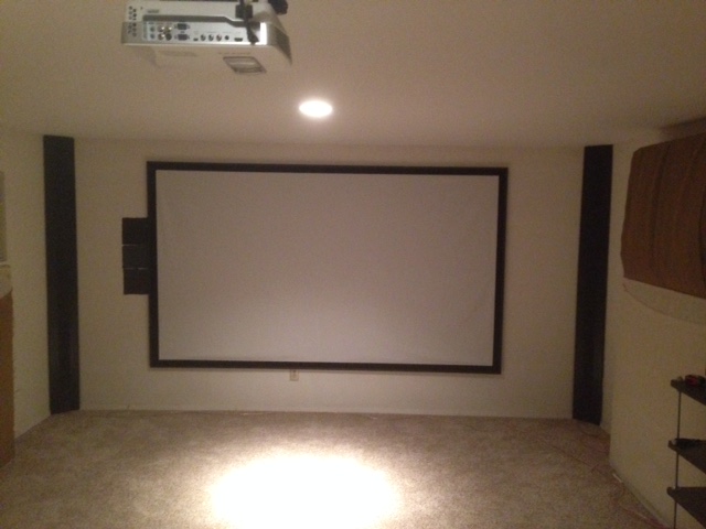
Hi RA7 - if you were to get a screen today, would you do a paint on screen? I'm considering the goo systems reference white pair product instead of the framed screen I had originally considered after reading about your null issue. Not sure if you could actually hear the difference after fixing the issue or not though so I thought I would ask what you would do if you were to make that decision again today.
Hi oneplustwo, a paint-on screen is a good idea. If you can get quality paint that doesn't degrade picture quality, go for it!
I didn't do enough testing to see if I could hear a difference. I felt much peer pressure and so I had to do something about it 🙂 But it was a pretty strong reflection because the edge ran parallel to the line array. If you did some sort of averaging measurement from multiple locations around the couch, maybe it would go away. Hope this helps.
I didn't do enough testing to see if I could hear a difference. I felt much peer pressure and so I had to do something about it 🙂 But it was a pretty strong reflection because the edge ran parallel to the line array. If you did some sort of averaging measurement from multiple locations around the couch, maybe it would go away. Hope this helps.
Hi ra7!
I'm trying to simulate corner line arrays to be able to design a waveguide. Your speakers are the ones that look most like what I'm planning, so I have some questions:
Whats the width of the baffle (looks like 20-25 cm)? What's the CTC-distance for the speakers (looks like 84 mm)?
Do you have any measurements at other horisontal angles? How much off-axis are you in the sweet spot (measuring point)? 15 degrees?
/Anton
I've painted two different screens using this advice/method.
Painting the Perfect Screen for $100
Excellent results. For one, I built a frame. For the other I used black gaffers tape for the border. Both look great.
Painting the Perfect Screen for $100
Excellent results. For one, I built a frame. For the other I used black gaffers tape for the border. Both look great.
Simulation result
Hi again!
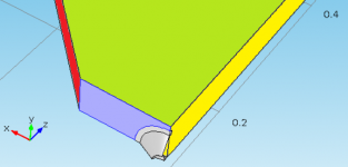
I did a sim with a 20 cm wide baffle and an approximated geometry for the TC9. It looks like this:
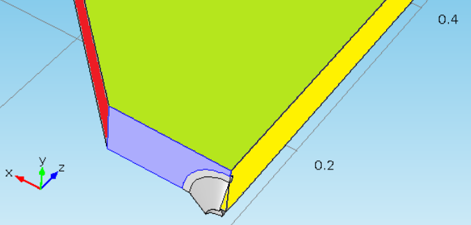
Blue is baffle, red is wall, yellow is centre symmetry, grey is driver membrane and green is vertical symmetry.
I'm assuming that
- the line array keeps its 84 mm ctc distance all the way to the floor and ceiling
- the membrane keeps a pistonic motion from 100 Hz to 16 kHz.
- walls are rigid
- the corner is infinitely deep (no other walls, infinite room). Equals a gated measurement before first reflection.
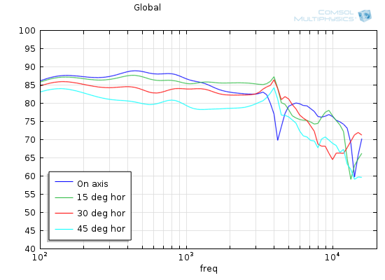
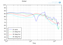
This is the resulting frequency response in the far-field at 15, 30 and 45 degrees off axis:
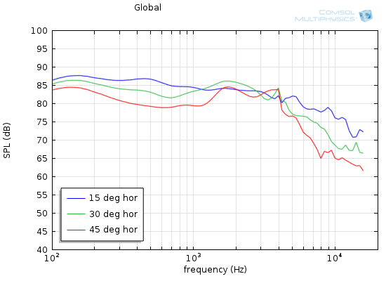
Not bad, especially the 15 degree curve.
Here is one with on-axis response as well:
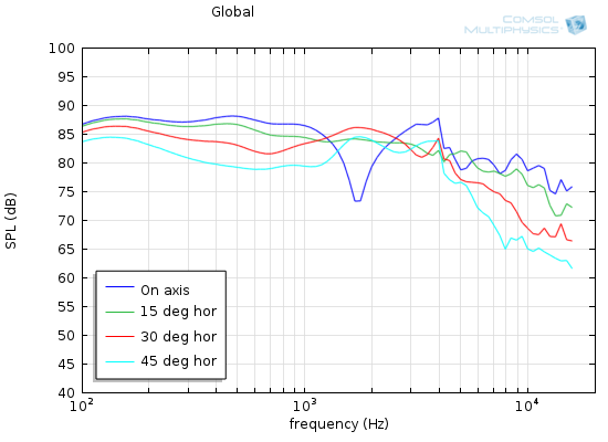
Here we see that the on-axis response has a dip at 1700 Hz. I'm assuming this is due to the discontinuity when the baffle meets the wall. Half wavelength for 1700 Hz is 0.1 m, which is identical to half baffle width.
I'll be at least close to on-axis with my line arrays when sitting at the outer positions in the couch. I take it that you are far enough back in the room to avoid this?
/Anton
Hi again!
I did a sim with a 20 cm wide baffle and an approximated geometry for the TC9. It looks like this:
Blue is baffle, red is wall, yellow is centre symmetry, grey is driver membrane and green is vertical symmetry.
I'm assuming that
- the line array keeps its 84 mm ctc distance all the way to the floor and ceiling
- the membrane keeps a pistonic motion from 100 Hz to 16 kHz.
- walls are rigid
- the corner is infinitely deep (no other walls, infinite room). Equals a gated measurement before first reflection.
This is the resulting frequency response in the far-field at 15, 30 and 45 degrees off axis:
Not bad, especially the 15 degree curve.
Here is one with on-axis response as well:
Here we see that the on-axis response has a dip at 1700 Hz. I'm assuming this is due to the discontinuity when the baffle meets the wall. Half wavelength for 1700 Hz is 0.1 m, which is identical to half baffle width.
I'll be at least close to on-axis with my line arrays when sitting at the outer positions in the couch. I take it that you are far enough back in the room to avoid this?
/Anton
Attachments


Hi ra7!
I'm trying to simulate corner line arrays to be able to design a waveguide. Your speakers are the ones that look most like what I'm planning, so I have some questions:
Whats the width of the baffle (looks like 20-25 cm)? What's the CTC-distance for the speakers (looks like 84 mm)?
Do you have any measurements at other horisontal angles? How much off-axis are you in the sweet spot (measuring point)? 15 degrees?
/Anton
Hi Anton,
The baffle width is 15.2 cm (6 inches). I went for as small a baffle as possible. CTC is 84 mm.
I am about 15 degrees off-axis in the listening spot right now. I don't think I measured the horizontal off-axis response, but it will be identical to that of a single TC9.
Hi again!
I did a sim with a 20 cm wide baffle and an approximated geometry for the TC9. It looks like this:
Blue is baffle, red is wall, yellow is centre symmetry, grey is driver membrane and green is vertical symmetry.
I'm assuming that
- the line array keeps its 84 mm ctc distance all the way to the floor and ceiling
- the membrane keeps a pistonic motion from 100 Hz to 16 kHz.
- walls are rigid
- the corner is infinitely deep (no other walls, infinite room). Equals a gated measurement before first reflection.
This is the resulting frequency response in the far-field at 15, 30 and 45 degrees off axis:
Not bad, especially the 15 degree curve.
Here is one with on-axis response as well:
Here we see that the on-axis response has a dip at 1700 Hz. I'm assuming this is due to the discontinuity when the baffle meets the wall. Half wavelength for 1700 Hz is 0.1 m, which is identical to half baffle width.
I'll be at least close to on-axis with my line arrays when sitting at the outer positions in the couch. I take it that you are far enough back in the room to avoid this?
/Anton
Wow, excellent sims. I'm having trouble understanding your first diagram, but the sims look believable. Like I said, I did not measure off-axis horizontally. I am far enough back that I sit at about 15 degrees off-axis.
I did have problems with the baffle to wall interface and there were some reflections from it. I solved most of it by adding a thin piece of cardboard to make a sort of waveguide that went from the driver to the wall. This helped get rid of some of the reflections. Although my solution was temporary at the time, it has stayed in place for over a year, mostly because I haven't had time to look into it.
You might want to push the drivers as far back inside the corner as possible so that the frequency where you get the dip gets pushed higher. I tried hard to correlate the dip to the baffle width but I recall that it did not match.
Alright, I'll remake the sim with 15.2 cm wide baffle. The photos disagree though... If I measure the width in the photo from the first post I get that baffle width is about 2.5 times that of the driver. 84*2.5 = 210 mm. Maybe 152 mm internal?Hi Anton,
The baffle width is 15.2 cm (6 inches). I went for as small a baffle as possible. CTC is 84 mm.
I am about 15 degrees off-axis in the listening spot right now. I don't think I measured the horizontal off-axis response, but it will be identical to that of a single TC9.
About horisontal response: If it was a wall integrated infinite baffle line array I would agree that the horisontal response would be very similar to a single TC9. But the enclosure will always affect the response due to diffraction otherwise.
What about the sim is hard to understand. The geometry?Wow, excellent sims. I'm having trouble understanding your first diagram, but the sims look believable. Like I said, I did not measure off-axis horizontally. I am far enough back that I sit at about 15 degrees off-axis.
I did have problems with the baffle to wall interface and there were some reflections from it. I solved most of it by adding a thin piece of cardboard to make a sort of waveguide that went from the driver to the wall. This helped get rid of some of the reflections. Although my solution was temporary at the time, it has stayed in place for over a year, mostly because I haven't had time to look into it.
You might want to push the drivers as far back inside the corner as possible so that the frequency where you get the dip gets pushed higher. I tried hard to correlate the dip to the baffle width but I recall that it did not match.
Do you have photos of the cardboard? Did you add it to both sides? Making the baffle asymmetrical is almost always a good idea to reduce diffraction issues. Are they visible in this photo?
In that case you did something that strongly resembles my plan 🙂
/Anton
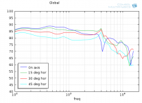
The addition of the cardboard waveguide essentially reduces the width of the baffle to ~76 mm. I made a simulation of that:
The reponse below 3 kHz is greatly improved compared to a 200 mm wide baffle:

(I remade this sim with a more detailed geometry for the TC9).
It makes the first dip narrower and at a higher frequency, which should sound better. Moving the dip even higher in frequency is probably preferable if you want to listen on-axis. That might be possible to achieve by rear-mounting the drivers and adding a separate waveguide to each driver.
/Anton
The reponse below 3 kHz is greatly improved compared to a 200 mm wide baffle:
(I remade this sim with a more detailed geometry for the TC9).
It makes the first dip narrower and at a higher frequency, which should sound better. Moving the dip even higher in frequency is probably preferable if you want to listen on-axis. That might be possible to achieve by rear-mounting the drivers and adding a separate waveguide to each driver.
/Anton
Attachments
- Home
- Loudspeakers
- Multi-Way
- Corner Floor-to-Ceiling Line Array Using Vifa TC9