Vacuum Tube LTspice tutorial?
Hello All,
Ltspice just loaded on the new win10pc.
Is there a tutorial posted somewhere for locating, installing a vacuum tube library including symbols and including how to call tube models in a circuit.
Thanks DT
Hello All,
Ltspice just loaded on the new win10pc.
Is there a tutorial posted somewhere for locating, installing a vacuum tube library including symbols and including how to call tube models in a circuit.
Thanks DT
Hello All,
Ltspice just loaded on the new win10pc.
Is there a tutorial posted somewhere for locating, installing a vacuum tube library including symbols and including how to call tube models in a circuit.
Thanks DT
Symbols are included already. Download the ayumi models. The ".inc" files are the models you will use. For each model that you are going to use open the inc file in a text editor and change any "^" to "**" and save.
Now in your schematics use an "include" directive to include the inc file for any models you will be using. Now on the symbol in your schematic change the name to the name used in the include file. Usually it is the same as the file name but not always. For some reason the the call for the 6N1P.inc is 6N1P_AN. That should do it.
Here is E810F model base of :: View topic - Updated TETRODE.TXT file by Stephie Bench. Formulae in original paint tool has been replaced so to impose sharp cut off limit which paint tool is unable to do. Maybe these changes can be included in paint tool in future I hope.
.SUBCKT E810F 1 2 3 4 ; P G K G2
+ PARAMS: CCG=14.5P CGP=0.036P CCP=3.5P RGI=1000
+ MU=57 KG1=101 KP=550 KVB=3 KVC=2.24 VCT=0.05 EX=1.35 ; KG2=370.1 not used.
* Vp_MAX=250 Ip_MAX=200 Vg_step=0.5 Vg_start=0 Vg_count=6
* Rp=1600 Vg_ac=23.5 P_max=5 Vg_qui=-23.4 Vp_qui=240 UL=0.43 EG2=150
* X_MIN=97 Y_MIN=47 X_SIZE=904 Y_SIZE=726 FSZ_X=1792 FSZ_Y=895 XYGrid=true
* showLoadLine=n showIp=y isDHP=n isPP=n isAsymPP=n isUL=n showDissipLimit=y
* showIg1=y gridLevel2=n isInputSnapped=n
* XYProjections=n harmonicPlot=y harmonics=y
*----------------------------------------------------------------------------------
RE1 7 0 1G ; DUMMY SO NODE 7 HAS 2 CONNECTIONS
E1 7 0 VALUE= ; E1 BREAKS UP LONG EQUATION FOR G1.
+{V(4,3)/KP*LOG(1+EXP((1/MU+(VCT+V(2,3))/V(4,3))*KP))}
G1 1 3 VALUE={limit((PWR(V(7),EX)+PWRS(V(7),EX))/KG1*1.57*ATAN(2*V(1,3)/(KVB*3.14159)),0,v(1,3)/670)}
;change /710 to /670, change the slope
; added limit-better models lower plate voltage limit condion
G2 4 3 value= {(I(G1)*27/(V(1,3) + 15))}
E2 8 4 VALUE={0} ; Dummy
RCP 1 3 1G ; FOR CONVERGENCE
C1 2 3 {CCG} ; CATHODE-GRID 1
C2 1 2 {CGP} ; GRID 1-PLATE
C3 1 3 {CCP} ; CATHODE-PLATE
R1 2 5 {RGI} ; FOR GRID CURRENT
D3 5 3 DX ; FOR GRID CURRENT
.MODEL DX D(IS=1N RS=1 CJO=10PF TT=1N)
.ENDS
*$
Attachments
Hello All,
Ltspice just loaded on the new win10pc.
Is there a tutorial posted somewhere for locating, installing a vacuum tube library including symbols and including how to call tube models in a circuit.
Thanks DT
lots of youtube tutorials -- in this case you use a ".lib" file which copies the library to the local directory.
about 5 minutes into this video -- YouTube
Is there pentode spice model available somewhere for 6AH6, 6AC7, 6j5p or 6j4 ? (they are all the same tube).
Is there pentode spice model available somewhere for 6AH6, 6AC7, 6j5p or 6j4 ? (they are all the same tube).
From: :: View topic - Updated TETRODE.TXT file
(plot of the model against the original maybe required to verify the accuracy)
.SUBCKT 6AC7 1 4 2 3
+ PARAMS: MU=49.9 EX=1.47 KG1=435 KP=162 KVB=12.3 ; KG2=415
+ CCG=11P CPG1=.015P CCP=5P RGI=2K
RE1 7 0 1MEG ; DUMMY SO NODE 7 HAS 2 CONNECTIONS
E1 7 0 VALUE= ; E1 BREAKS UP LONG EQUATION FOR G1.
+{V(4,3)/KP*LOG(1+EXP((1/MU+V(2,3)/V(4,3))*KP))}
G1 1 3 VALUE={(PWR(V(7),EX)+PWRS(V(7),EX))/KG1*ATAN(V(1,3)/KVB)}
*G2 4 3 VALUE={(EXP(EX*(LOG((V(4,3)/MU)+V(2,3)))))/KG2}
g2 4 3 value= {(I(G1)*100/(V(1,3) + 100))} ; models change in current with change in plate
RCP 1 3 1G ; FOR CONVERGENCE
C1 2 3 {CCG} ; CATHODE-GRID 1
C2 1 2 {CPG1} ; GRID 1-PLATE
C3 1 3 {CCP} ; CATHODE-PLATE
R1 2 5 {RGI} ; FOR GRID CURRENT
D3 5 3 DX ; FOR GRID CURRENT
*.MODEL DX D(IS=1N RS=1 CJO=10PF TT=1N)
.ENDS
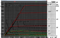
Noted the screen current.
.SUBCKT 6AC7 1 2 3 4
+ PARAMS: MU=49.9 EX=1.39 KG1=632 KP=162 KVB=8 VCT =0; KG2=415
+ CCG=11P CPG1=.015P CCP=5P RGI=2K
RE1 7 0 1MEG ; DUMMY SO NODE 7 HAS 2 CONNECTIONS
E1 7 0 VALUE= ; E1 BREAKS UP LONG EQUATION FOR G1.
+{V(4,3)/KP*LOG(1+EXP((1/MU+(VCT+V(2,3))/V(4,3))*KP))}
G1 1 3 VALUE={limit((PWR(V(7),EX)+PWRS(V(7),EX))/KG1*1.57*ATAN(2*V(1,3)/(KVB*3.14159)),0,v(1,3)/3200)}
;change /710 to /670, change the slope
; added limit-better models lower plate voltage limit condion
G2 4 3 value= {(I(G1)*900/(V(1,3) +2800))}
RCP 1 3 1G ; FOR CONVERGENCE
C1 2 3 {CCG} ; CATHODE-GRID 1
C2 1 2 {CPG1} ; GRID 1-PLATE
C3 1 3 {CCP} ; CATHODE-PLATE
R1 2 5 {RGI} ; FOR GRID CURRENT
D3 5 3 DX ; FOR GRID CURRENT
.MODEL DX D(IS=1N RS=1 CJO=10PF TT=1N)
.ENDS
Attachments
Please use the search function before asking for a model, there is a model for the 6AC7/6J4P included in http://www.diyaudio.com/forums/atta...cuum-tube-spice-models-tube-models-ja2dhc.zip on the first page of the thread.
Thanks @Koonw - however, there is error message from LTSPICE: "Iteration Limit Reached" on both (changed pin order on 6AC7 but still no go)
Thanks @jazbo8 - did not show up when I searched for it, maybe my fault ...
the els-ja2dhc.zip has a typo in the 6j4pp data - 2 decimal points in X3 parameter; also needs carets ^ replaced by ** for LTSPICE, seems to workthen.
Thanks @jazbo8 - did not show up when I searched for it, maybe my fault ...
the els-ja2dhc.zip has a typo in the 6j4pp data - 2 decimal points in X3 parameter; also needs carets ^ replaced by ** for LTSPICE, seems to workthen.
Try something simple first. Plot the curve using the attach schematic. Also ensure the pins in pentode.asy file match the model
.SUBCKT 6AC7 1 2 3 4 ; A G K G2
1=A, G=2, 3=K, 4=G2
If not you have to change the pin, either the model file or the pentode.asy and save as pentode2.asy.
.SUBCKT 6AC7 1 2 3 4 ; A G K G2
1=A, G=2, 3=K, 4=G2
If not you have to change the pin, either the model file or the pentode.asy and save as pentode2.asy.
Attachments
Pin order....😉
Use the tetrode symbol included in LTspice (tetrode.asy) in your schematic.
Code:
.SUBCKT 6AC7 1 4 2 3 ; P S G K
+ PARAMS: MU=49.9 EX=1.39 KG1=632 KP=162 KVB=8 VCT =0; KG2=415
+ CCG=11P CPG1=.015P CCP=5P RGI=2K
RE1 7 0 1MEG ; DUMMY SO NODE 7 HAS 2 CONNECTIONS
E1 7 0 VALUE= ; E1 BREAKS UP LONG EQUATION FOR G1.
+{V(4,3)/KP*LOG(1+EXP((1/MU+(VCT+V(2,3))/V(4,3))*KP))}
G1 1 3 VALUE={limit((PWR(V(7),EX)+PWRS(V(7),EX))/KG1*1.57*ATAN(2*V(1,3)/(KVB*3.14159)),0,v(1,3)/3200)}
;change /710 to /670, change the slope
; added limit-better models lower plate voltage limit condion

G2 4 3 value= {(I(G1)*900/(V(1,3) +2800))}
RCP 1 3 1G ; FOR CONVERGENCE
C1 2 3 {CCG} ; CATHODE-GRID 1
C2 1 2 {CPG1} ; GRID 1-PLATE
C3 1 3 {CCP} ; CATHODE-PLATE
R1 2 5 {RGI} ; FOR GRID CURRENT
D3 5 3 DX ; FOR GRID CURRENT
.MODEL DX D(IS=1N RS=1 CJO=10PF TT=1N)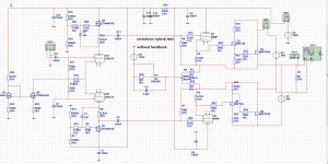
.ENDSwith pin order 1 4 2 3 both 6AC7 models work in simple circuits, but when complexity is higher - in my case see-saw splitter a la quad-ii - the convergence problem shows up;
so, I turned to the Ayumi model which works fine, this one from jazbo8's link (fixed the typo with extra decimal point in X3 parameter and ** instead of ^ for LTSPICE) :
* Generic pentode model: 6J4P aka 6j5p aka 6AC7 aka 6AH6
* Copyright 2003--2008 by Ayumi Nakabayashi, All rights reserved
* Version 3.10, Generated on Mon Oct 05 17:00:49 2009
* Plate
* | Screen Grid
* | | Control Grid
* | | | Cathode
* | | | |
.SUBCKT 6J4PP A S G K
.PARAM X1=0.35903154 X2=0.0051230024 X3=-0.3031279
.PARAM X4=0.83188775 X5=32.815182 X6=1.8031279
.PARAM X7=0.0040192654 X8=39.446647 X9=0.00247534
.PARAM Y1=0.0020096327 Y2=0.7737796 Y3=0.2262204
.PARAM Y4=0.002163434 EA=14848.5
BK IK 0 V=U(V(G,K)+X1)*X7*URAMP(V(G,K)+X1+URAMP(V(S,K))/X8)**1.5+(1-U(V(G,K)+X1))*X9*(X2*URAMP(V(S,K)))**X3*(X4*URAMP(V(G,K)+X1+URAMP(V(S,K))/X5))**X6
BL IL 0 V=(V(IK)-Y1*URAMP(V(G,K))**1.5*(URAMP(V(G,K))/(URAMP(V(A,K))+URAMP(V(G,K)))*1.2+.4))*(1-.4*(EXP(-URAMP(V(A,K))/URAMP(V(S,K))*15)-EXP(-15)))
BM IM 0 V=V(IL)*(URAMP(V(A,K))+EA)/(URAMP(V(S,K))+EA)-URAMP(V(IL)*(URAMP(V(A,K))+EA)/(URAMP(V(S,K))+EA)-(Y4*(URAMP(V(A,K))+URAMP(URAMP(V(S,K))-URAMP(V(A,K))))**1.5))
BA A K I=URAMP(Y4*URAMP(V(A,K))**1.5-URAMP(Y4*URAMP(V(A,K))**1.5-V(IM)+V(IL)*(Y2*(1-URAMP(V(A,K))/(URAMP(V(A,K))+10))**1.5+Y3)))+1E-10*V(A,K)
BS S K I=URAMP(V(IM)-URAMP(Y4*URAMP(V(A,K))**1.5-URAMP(Y4*URAMP(V(A,K))**1.5-V(IM)+V(IL)*(Y2*(1-URAMP(V(A,K))/(URAMP(V(A,K))+10))**1.5+Y3))))
BG G K I=Y1*URAMP(V(G,K))*1.5*(URAMP(V(G,K))/(URAMP(V(A,K))+URAMP(V(G,K)))*1.2+.4)
* CAPS
CGA G A 0.015p
CGK G K 6.6p
CGS G S 4.4p
CAK A K 6p
.ENDS
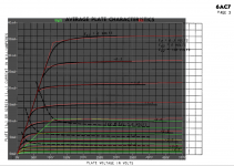
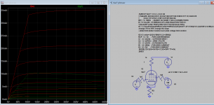
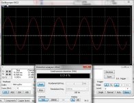
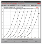
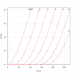
Has this one but do not now it is oke but it do work and good respons see pictures.
.subckt 6N6P 1 2 3
+ params: mu=18.8 ex=1.666 kg1=810 kp=85.5 kvb=600 rgi=2000 vct=.02
+ ccg=4.4p cgp=1.7p ccp=1.85p
e1 7 0 value=
+{v(1,3)/kp*log(1+exp(kp*(1/mu+v(2,3)/sqrt(kvb+v(1,3)*v(1,3)))))}
re1 7 0 1g
g1 1 3 value= {(pwr(v(7),ex)+pwrs(v(7),ex))/kg1}
rcp 1 3 1g
c1 2 3 {ccg}
c2 1 2 {cgp}
c3 1 3 {ccp}
r1 2 5 {rgi}
v1 5 6 {vct}
d3 6 3 dx
.model dx d(is=1n rs=1 cjo=1pf tt=1n)
.ends
Attachments
Last edited:
Anyone have a good model of the Russian 6N6P high Gm triode?
Code:
* ==============================================================
* 6N6P LTSpice model
* Koren model (5 parameters): mean fit error 0.591392mA
* Traced by Wayne Clay on 12/23/2016 using Curve Captor v0.9.1
* and Engauge Digitizer from Soviet datasheet
* ==============================================================
.subckt 6N6P  P G K
    Bp  P K  I=(0.01775316952m)*uramp(V(P,K)*ln(1.0+exp((7.538517656)+
+ (7.538517656)*(16.95526988)*V(G,K)/sqrt((-0.006038270499k)+
+ (V(P,K))**2)))/(7.538517656))**(1.665343065)
  Cgp G P 4.2p ; 0.7p added (3.5p)
  Cgk G K 5.1p ; 0.7p added (4.4p)
  Cpk P K 1.9p ; 0.2p added (1.7p)
  Rpk P K 1.0G ; to avoid floating nodes in mu-follower
  d3  G K dx1
.model dx1 d(is=1n rs=2k cjo=1pf N=1.5 tt=1n)
.ends 6N6P
Attachments
6N6P Ayumi model
Code:
*
* Generic triode model: 6N6P
* Copyright 2003--2008 by Ayumi Nakabayashi, All rights reserved.
* Version 3.10, Generated on Wed Mar  8 12:22:20 2017
*               Plate
*               | Grid
*               | | Cathode
*               | | |
.SUBCKT 6N6P_AN A G K
BGG   GG   0 V=V(G,K)+-0.25601741
BM1   M1   0 V=(0.021339633*(URAMP(V(A,K))+1e-10))**-0.6377381
BM2   M2   0 V=(0.70167622*(URAMP(V(GG)+URAMP(V(A,K))/13.979799)+1e-10))**2.1377381
BP    P    0 V=0.0037683642*(URAMP(V(GG)+URAMP(V(A,K))/19.923433)+1e-10)**1.5
BIK   IK   0 V=U(V(GG))*V(P)+(1-U(V(GG)))*0.002184066*V(M1)*V(M2)
BIG   IG   0 V=0.0018841821*URAMP(V(G,K))**1.5*(URAMP(V(G,K))/(URAMP(V(A,K))+URAMP(V(G,K)))*1.2+0.4)
BIAK  A    K I=URAMP(V(IK,IG)-URAMP(V(IK,IG)-(0.0021714264*URAMP(V(A,K))**1.5)))+1e-10*V(A,K)
BIGK  G    K I=V(IG)
* CAPS
CGA   G    A 4.2p ; 0.7p added (3.5p)
CGK   G    K 5.1p ; 0.7p added (4.4p)
CAK   A    K 1.9p ; 0.2p added (1.7p)
.ENDS
Attachments
Hello community!
Does anyone know where to get or how to model the PL21 pentode and PL522 triode for LTspice?
Any help would be much appreciated.
Regards,
Anna
Does anyone know where to get or how to model the PL21 pentode and PL522 triode for LTspice?
Any help would be much appreciated.
Regards,
Anna
- Home
- Amplifiers
- Tubes / Valves
- Vacuum Tube SPICE Models