A recap of what we know and possible causes. Please correct any mistakes I have made.
1. Two amp boards with the same problem. - Error in the layout. - A bad layout. - Wrong component values. - PSU.
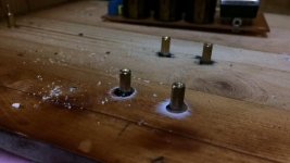
2. Smoking negative rail capacitor. - Polarity or over voltage/current.
3. PSU DC voltages correct.
4. Transformer AC voltages correct.
5. Polarity capacitors correct.
6. Full negative voltage at the output with no load connected. - Feedback loop not completed. - Chip failed.
7. Something else.
1. Two amp boards with the same problem. - Error in the layout. - A bad layout. - Wrong component values. - PSU.
2. Smoking negative rail capacitor. - Polarity or over voltage/current.
3. PSU DC voltages correct.
4. Transformer AC voltages correct.
5. Polarity capacitors correct.
6. Full negative voltage at the output with no load connected. - Feedback loop not completed. - Chip failed.
7. Something else.
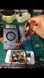
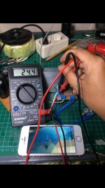
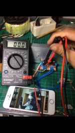
try to connect a resistor at the output to ground and measure again. There is no load right now, its open.
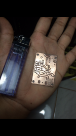
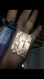
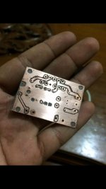
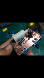
hi all here's the update.
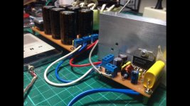
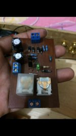
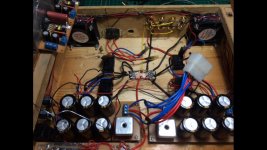
im making a new board with new layout(using chip from the old board), i made(or craft?) tiny minimus board from xtronic and ITS WORKING, this tiny board are really working! this double layer board really time consuming, takes me 5 Hours to make one from scratch, some cap & 5watt R i put at bottom side because they are not fit at top board. i agree if this could be the ugliest board you've ever see, my laserjet is shor of toner i using marker for damage area, but again, its working. believe me I add my very big smile here
i would like to say thank you to all of you that assist me to make this project posible to me. i may stuck at the begining without ending(like dormammu) without your help, again, many thanks 🙂
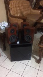
can i make this thread to WIP(work in progress) thread?? i really want to share my diy case & its diy speakers when its done 😀
or i should make another thread??
Best.
Bobby
ps: the pink phone is not mine, that is my sister's phone 😱
Attachments
-
 IMG_6839.PNG948.1 KB · Views: 220
 -
 IMG_6840.PNG940.8 KB · Views: 201
 -
 IMG_6841.jpg62.6 KB · Views: 192
 -
 IMG_6842.jpg59.1 KB · Views: 195
 -
 IMG_6843.PNG722 KB · Views: 199
 -
 IMG_6845.PNG657.5 KB · Views: 134
 -
 IMG_6849.jpg86.6 KB · Views: 122
 -
 IMG_6848.jpg83.8 KB · Views: 108
 -
 IMG_6847.jpg86.5 KB · Views: 118
Last edited:
Yes it is. It reminds me of the boards I used to make with Dalo pens.
One final though on these caps. Why not unsolder one that is getting hot and tag it across one of the main power supply caps (observing polarity of course). It should then run absolutely cold if the cap is OK.
Just a thought 🙂
One final though on these caps. Why not unsolder one that is getting hot and tag it across one of the main power supply caps (observing polarity of course). It should then run absolutely cold if the cap is OK.
Just a thought 🙂
same power supply?
Who ? me 🙂
Yes, same power supply because the caps on that board seem to survive.
If the tagged on cap does survive OK then we know there is an issue with the wiring or board of the amp. If it doesn't then we know either the cap or power board has an issue.
same power supply?
Same power supply 😀
Yes it is. It reminds me of the boards I used to make with Dalo pens.
One final though on these caps. Why not unsolder one that is getting hot and tag it across one of the main power supply caps (observing polarity of course). It should then run absolutely cold if the cap is OK.
Just a thought 🙂
Im using them for fan & protector power supply, has been tested and they are completely fine sir, just bad layout at first
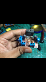
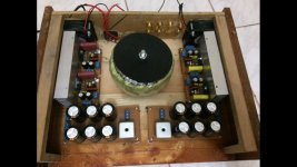
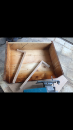
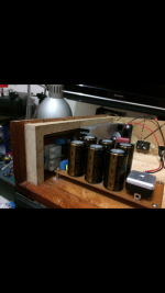
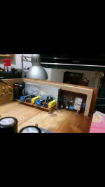
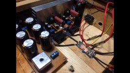
Im making a progress right now. the last double sided board getting hot so fast and make short circuit(maybe) then burn the ic & the testbulb are glowing so bright(hot at the board not chip) then i change my layout(again) with more simple single layer from diyfan.blogspot they are easy to make, i make 4 of them, my plan to build 4.0 amplifier in one box for my 5.1 project, here is some picture, still in progress, just ordered 2 new chip at my distributor & they will come in few days. im using some dead chip for fitting purpose. Using pcb spacer for pcb mounting, drill 3mm hole and glue them with super glue to the case, this case is upside down, thw pcb are mounted at the top side of the case only the transformer mounted at bottom plate (due to its weight). Im using ex pallet wood to make the case, i know my heatsink is a bit too small so im using 2 dc fan for cooling it, tested for 24hours playing music and its not so hot
Best
Bobby.
Attachments
-
 IMG_6930.jpg66.1 KB · Views: 110
 -
 IMG_6931.jpg96.7 KB · Views: 92
 -
 IMG_6926.jpg64.2 KB · Views: 81
 -
 IMG_6928.jpg78.8 KB · Views: 97
 -
 IMG_6924.jpg73.2 KB · Views: 108
 -
 IMG_6925.jpg71.9 KB · Views: 109
 -
 IMG_6937.jpg65.6 KB · Views: 103
 -
 IMG_6934.PNG690.6 KB · Views: 90
 -
 IMG_6933.jpg82 KB · Views: 91
 -
 IMG_6932.jpg77.7 KB · Views: 91
Last edited:
Quick question
I wonder, can ii make a bridge these 2 seperated board(in single heatsink)together?? Then i got only stereo(but more powerful) with this amp ? Before i work next sub & center channel .
I wonder, can ii make a bridge these 2 seperated board(in single heatsink)together?? Then i got only stereo(but more powerful) with this amp ? Before i work next sub & center channel .
That's all looking good 
I'm not quite sure what you asking in the last question. Do you mean you want to bridge the amplifiers to make a single more powerful one ? If so then you need some means of driving one with an out of phase signal, which can be done with an opamp.
I'm not quite sure what you asking in the last question. Do you mean you want to bridge the amplifiers to make a single more powerful one ? If so then you need some means of driving one with an out of phase signal, which can be done with an opamp.
That's all looking good
I'm not quite sure what you asking in the last question. Do you mean you want to bridge the amplifiers to make a single more powerful one ? If so then you need some means of driving one with an out of phase signal, which can be done with an opamp.
For now i want to tied 2 chips for making jn one channel, so i got only 2 channel with this box sir, only when im done with center & sub amp then i change this to 4 channel again, can i do that without opamp sir ?? There is no space left in the box for even tone control/ preamp, i just recieved 8 fuse holder (2A) & wanted to install it for each rail, but my friend telling me that is not important & will only block the amperage from psu to the amp board, is that correct ??
Attachments
This shows a high performance phase splitter which could be built from a TLO74 quad opamp. You have to drive each power amp with identical but out of phase signals to make a bridged amplifier.
I'm not sure you will gain much by doing this because the LM3886 is a very decent and quite powerful chip in its own right.
Fuses are needed for safety. You should fuse the incoming mains supply and also the AC feeds to the bridge rectifiers.
I'm not sure you will gain much by doing this because the LM3886 is a very decent and quite powerful chip in its own right.
Fuses are needed for safety. You should fuse the incoming mains supply and also the AC feeds to the bridge rectifiers.
Attachments

Heres some update,
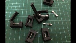
I make pair little bur nice protector that i got from videorockola, i placed them at wall side of the case, its nice to have some space for them
Will use fuse then 😀, now im decided to NOT bridge them, its too complicated for me haha, any advice for this amp sir ?? Maybe my placement is not right ? Chips to close to transformer or something ??
I make pair little bur nice protector that i got from videorockola, i placed them at wall side of the case, its nice to have some space for them
That's all looking good
I'm not quite sure what you asking in the last question. Do you mean you want to bridge the amplifiers to make a single more powerful one ? If so then you need some means of driving one with an out of phase signal, which can be done with an opamp.
This shows a high performance phase splitter which could be built from a TLO74 quad opamp. You have to drive each power amp with identical but out of phase signals to make a bridged amplifier.
I'm not sure you will gain much by doing this because the LM3886 is a very decent and quite powerful chip in its own right.
Fuses are needed for safety. You should fuse the incoming mains supply and also the AC feeds to the bridge rectifiers.
Will use fuse then 😀, now im decided to NOT bridge them, its too complicated for me haha, any advice for this amp sir ?? Maybe my placement is not right ? Chips to close to transformer or something ??
Attachments
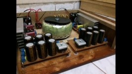
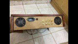
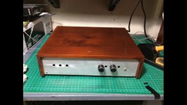
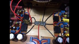
Here's is some update, just finished the wiring, use star grounding that i learn from another thread and its work like a charm! No noise no hum, compelety silent when idle 😀, im wiring the amps for 2x stereo purpose, until im working center & sub amp, have some used small psu board then i convert it for fan & protector power supply(next to the transformer), tomorrow will install the power switch 😀
Best
Bobby.
(Got 2 air nailer coming thru the top case is SO ANNOYING)
Best
Bobby.
(Got 2 air nailer coming thru the top case is SO ANNOYING)
Attachments

Well done
thank you sir, 😀
now im using 2x stereo 10K pot for the job, but i dont get gain that i want, not much diference with my old LM1875 based that my father made for me many years ago(4x 60watt IC only producing same gain with 2x 18watt IC driving same speakers
 ), should i change with 50K or 100K pot sir ?? or something i can do to increase the gain, for now im using 18-0-18 from my traffo, should i change it to 24-0-24 / 32-0-32 ??
the amps driving 4 small bookshelf speaker with 6" speaker & 3,5" tweeter each
Attachments
Last edited:
Increase 10k at input to 22k and yes increase voltage that would give u more power.thank you sir, 😀
now im using 2x stereo 10K pot for the job, but i dont get gain that i want, not much diference with my old LM1875 based that my father made for me many years ago(4x 60watt IC only producing same gain with 2x 18watt IC driving same speakers
the amps driving 4 small bookshelf speaker with 6" speaker & 3,5" tweeter each
The only way to get more gain is to either add a preamplifier or alter the feedback factor of the power amps.
Reducing Ri and increasing Ci in proportion will give more gain. So you could try 680 ohm and either a 33uF or 47uF. The cap determines the lower frequency response (how much bass)
Different transformer voltages will only increase the maximum available 'power' and will not alter gain.
Reducing Ri and increasing Ci in proportion will give more gain. So you could try 680 ohm and either a 33uF or 47uF. The cap determines the lower frequency response (how much bass)
Different transformer voltages will only increase the maximum available 'power' and will not alter gain.
Attachments

- Status
- Not open for further replies.
- Home
- Amplifiers
- Chip Amps
- My first amp & its blown (need help)