When using PS chokes in the low voltage leg rather than the high voltage leg should the common PS ground return point be at the transformer secondary or after the last PS choke?
mike
mike
When using PS chokes in the low voltage leg rather than the high voltage leg should the
common PS ground return point be at the transformer secondary or after the last PS choke?
Post your circuit, high voltage is involved.
When using PS chokes in the low voltage leg rather than the high voltage leg should the common PS ground return point be at the transformer secondary or after the last PS choke?
mike
After the last ripple filter choke, otherwise, you completely defeat the purpose of including them in the first place.
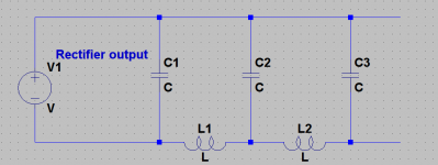
A common Pi filter PS but with the chokes in the low voltage (grounded) side
to use chokes of unknown case to winding insulation ratings.
Everything before the last choke must float WRT ground. Then the lower end
of the last capacitor can be grounded.
Why do you want to do it that way?
There was a 1950's article indicating that was prone to noisy output, depending on how your transformer secondary coupled to ground and chassis. Of course I can't identify the reference right now after a quick look!
The working voltage of the transformer secondary may also be increased, which may also stress that parts insulation.
There is a maximum voltage allowed between windings and core.With a very high voltage supply it's more safe to put the choke in the ground leg.
Mona
Mona
The ground goes in exactly the same place for the negative rail choke as it does for the more common positive rail choke: the negative of the last PSU smoothing capacitor (i.e. the output of the PSU). So after the last choke, but not necessarily immediately after if there are smoothing resistors too. Note that smoothing resistors can go in the negative rail too, but there is no advantage in doing this.
One big advantage of using a negative rail choke is that it makes it less likely for someone to simply ground the secondary CT. OK, a really confused person might do this for a negative rail choke and then wonder why the choke does not do anything. Grounding the CT with a positive rail choke has a more subtle effect: the choke works but you still get buzz.
One big advantage of using a negative rail choke is that it makes it less likely for someone to simply ground the secondary CT. OK, a really confused person might do this for a negative rail choke and then wonder why the choke does not do anything. Grounding the CT with a positive rail choke has a more subtle effect: the choke works but you still get buzz.
There is a maximum voltage allowed between windings and core.With a very high voltage supply it's more safe to put the choke in the ground leg.
Mona
If a PT with VAC-CT-VAC secondary was in a common full-wave rectified circuit with CT grounded and choke filtered, then its working voltage is effectively VACpk.
If a choke was inserted between CT and ground, then the secondary winding working voltage increases to VACpk + (VACpk - VDC), so perhaps about 30% increase. Not much in the scheme of things, but perhaps worth noting.
My most recent supply uses a completely symmetric schematic: equal valued chokes in both legs. I also like to include Q-killer resistors that prevent nasty peaks and dips in the impedance-vs-frequency curve (a/k/a self resonance). Only at the very end of the ladder is one or the other leg connected to "ground".
Why bother to make a symmetric arrangement of 2N chokes rather than an asymmetric arrangement of N chokes as in post #3 above? Because symmetry is pleasing. And the founder of Learjet has some advice about that: link
Why bother to make a symmetric arrangement of 2N chokes rather than an asymmetric arrangement of N chokes as in post #3 above? Because symmetry is pleasing. And the founder of Learjet has some advice about that: link
Self-resonance in PSU chokes is usually regarded as beneficial, because it maximises attenuation of any mains noise and switching spikes. The resonance which may need damping is that of the choke with the PSU capacitors, which will usually be at much lower frequency than any choke self-resonance.
Use a choke in both rails is a waste of money, space and time. There is no reason to do such a thing, although if a single core is shared by both rails is a better approach, in a proper wiring of it, say, fields must be additive..
Why do you want to do it that way?
There was a 1950's article indicating that was prone to noisy output, depending on how your transformer secondary coupled to ground and chassis. Of course I can't identify the reference right now after a quick look!
The working voltage of the transformer secondary may also be increased, which may also stress that parts insulation.
Yes, that's a problem as the stray capacitance between the secondary and core tends to bypass the ripple filter. Putting the choke(s) in the DC neutral does have advantages regarding insulation in high voltage supplies. These are usually found in max legal ham rigs where the added noise is of no consequence. It's RF and way above the mains frequency.
The other advantage, if using an L-input filter, is that you can half wave rectify the ripple pulses to get a "free" negative rail for biasing the finals.
For most audio projects, an L-input filter is needed, and your DC rail isn't high enough to justify it. That is unless you're building a monster amp that could fill a stadium with ear-splitting volume.
There was a 1950's article indicating that was prone to noisy output, .... Of course I can't identify the reference right now...
Looking in wrong decade?
August, 1934
Note On A Cause Of Residual Hum In Rectifier-Filter Systems
Frederick Emmons Terman And Sidney B. Pickles
200KB PDF
Doh, thanks PRR. I'd somehow lost that article in my pc folders - luckily I uploaded it in 2015.
Good ol' Terman, he was on to it!
I've measured similar capacitance from secondary HV winding to primary or electrostatic shield.
Good ol' Terman, he was on to it!
I've measured similar capacitance from secondary HV winding to primary or electrostatic shield.
The obvious fix is to implement a cascade of several transformers in series. The first (N-1) of them are just 115VAC-to-115VAC isolation transformers with 1:1 turns ratio {or 230V-to-230V where appropriate}.
Each transformer has an 0.22uF safety-rated X capacitor across the secondary. Thus each transformer attenuates capacitively coupled noise, by a factor of (Cprimary_to_secondary / 0.22uF) which is many dB. The cascade gives (many dB) times (N-1). Many many dB.
I mention "0.22uF" only because it is the capacitance value which has the largest stock on-the-shelf at DigiKey: 240,000 of them. Feel free to choose a different capacitance value for the safety-rated X capacitors, if you see fit.
Mark, I think Terman/Pickles were describing the distributed capacitance between a HV secondary winding and a chassis ground (that capacitance could be a collation of stray capacitance such as to transformer core, or bell ends, or primary winding, or heater winding, or even an electrostatic shield). And the secondary HV mains frequency waveform would then force hum current around their illustrated circuit.
Last edited:
> I've measured similar capacitance from secondary HV winding to primary or electrostatic shield.
Terman: "C1 as measured was 600 micromicrofarads." (now spelled "pFd")
This pretty much goes by transformer size; not voltage or current. Actually the surface area of the winding, from winding to winding or winding to core (what matters here). Very small jobs may be 100pFd. Very large (in our world) jobs may be 1,000pFd. This can limit the ripple reduction when the stray C bypasses inductors. It is why wide-band audio transformers can't be worked at very high impedances. C is everywhere and it usually sucks.
Transformer stray C "can" be reduced by clever winding layout. C can be reduced by thick insulation, but this reduces space for low DCR and high inductance. Terman could possibly have re-wound his lump with 10 or 20 sheets of Kraft (or couple layers of fishpaper) between winding and core; stock designs usually have that much space in reserve. That needs cash or labor.
Note that the same treatment on the *chokes* would give the >500V insulation rating to allow them to be used on the positive line. Rewinding one choke is a lot easier than rewinding a 3-winding transformer; Terman's students might manage it.
> implement a cascade of several transformers in series
Increased losses and cost.
Terman's conclusion was - "In the case that other considerations make it necessary to place some chokes in the negative lead, then the last section of filtering must have its impedance in the positive line."
Who cares about cost? We're not competing with Samsung, we're building our own gear that will give pleasure for years and years. The amortization schedule is looooooong.
- Home
- Amplifiers
- Power Supplies
- PS Choke in ground leg