I guess if cost wasn't such a concern then the hi-fi end of town that use valves should really make more use of electrostatic shielding within their power transformers.
A lot more diyers are aware of appropriately snubbing windings that are ss rectified, thanks to Mark's Quasimodo efforts. If DC heaters aren't used, then there is benefit in adding an ES layer between secondary HV and heater windings - Merlin illustrated that noise path back in 2010 (AX84.com - The Cooperative Tube Guitar Amp Project).
There is also benefit in adding a primary winding ES as well as a secondary winding ES (aka instrumentation power transformers) to alleviate mains borne interference, and to allow mains borne and HV winding hash and hum current to be routed to their most appropriate star points.
Sharing a choke positive and negative rail
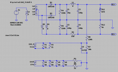
Resusciating an old thread, but wondering about the pros and cons of this circuit.
I have a couple of old 1930's radios where the choke is on the common leg in series with the field coil from the loudspeaker, and then the voltage drop across the field coil is used to derive a negative bias for the output tube. Seems very neat, and they are very quiet when they are working.
I have adapted a circuit designed for EL84s for PL84s, and have a much reduced B+ (210V instead of 310V), and this has impacted the operating point of the driver/concertina phase splitter). The idea is to create a negative rail from my 200-0-200 CT secondary on the power transformer, then I would have 400V across the driver/splitter, making it easier to find a sweet spot.
I have a choke that is currently in the positive rail, but was thinking it could just as easily be in the common rail. Ground would be taken from the junction of C3/C4.
Attachments

The change of B+ also changes the operating point of the power tubes. I can't imagine any EL84/PL84 power stage, short of a cathode follower, which could not be driven well with a concertina feed with a small drop from the power stage B+. At 200V the '84 only needs a couple Volts drive.
In your first image, when loaded, does ripple change when the (unstated) value of L3 changes? My guess is that it does not, or not-much, showing that L3 does little or nothing.
In your first image, when loaded, does ripple change when the (unstated) value of L3 changes? My guess is that it does not, or not-much, showing that L3 does little or nothing.
The concertina is DC coupled to the driver, so there is 70v across the driver, and 130 across the concertina. That seemed a bit miserly compared with the operating points of 100 and 200 respectively, from the original design.
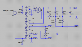
I did not simulate the PS, just used ltspice as a drawing tool. I find it hard to find models for transformers and chokes. The choke is the standard Triad C-14X, which is 6H and 200mA.
I did not simulate the PS, just used ltspice as a drawing tool. I find it hard to find models for transformers and chokes. The choke is the standard Triad C-14X, which is 6H and 200mA.
> hard to find models for transformers and chokes.
For basic function, use AC sources and ideal choke. LTspice has these.
For basic function, use AC sources and ideal choke. LTspice has these.
Hi PRR, thanks for tossing me the fishing pole, and not the fish. I've made myself sit down and learn a few more concepts, and now I think I have the solution.
The choke was my friend in one of the B+ supplies because it enables me to keep a lower voltage supply (210v), and then the other supply can be CRC, and then I get the extra headroom I need (265v).
The choke was my friend in one of the B+ supplies because it enables me to keep a lower voltage supply (210v), and then the other supply can be CRC, and then I get the extra headroom I need (265v).