It's come to my attention that I have to solve the bus pumping problem on my IRS2092 amp. I have 4 x IRS2092 L15DSMD boards. 2 for each speaker in bi-amping. All 4 on 1 SMPS.
I have read that 2 solutions can be either very big capacitance after the PSU. I have 2x 63V Elna's 10000uF in my drawer. Can I use these? Its a double voltage 55V PSU. If I put one in parallel (55V+ to GND and 55V- to GND) on each rail would this not create a short?
The other solution is phase inversion? What is the easiest way to invert the phase on the 2 left channel boards? My DAC actually has balanced output converted to phono? Does this make phase inversion easier if I put XLR inputs in my amp chassis (drawings pleeeease....)
As you already have balanced outputs its easy to phase invert one channel, just use the unused pin of the XLR output. So if you're currently connected to 1 (0V) and 3 (hot) then swap to pin 2 for hot. And vice versa.
Right now PIN3 and PIN1 are connected to phono shield, and PIN2 is inner. So on other cable I should use PIN3 as inner and connect PIN2 and PIN1 on shield. But wouldnt this cause a short?
Sounds like a true balanced output (either transformer or with electronic balancing). Given that pin2 and pin3 are complementary outputs if pin3 to pin1 doesn't cause a short, then neither will pin2 to pin1.
I just had a chat with Anders who recently upgrade my BMC-2 DAC. The XLR outputs are not true balanced outputs. Also a SMPS probably won't be happy on startup with 10000uF capacitance. So I'm back to square one.
Any knowledge of some phase inverter board kits on ebay or ali?
Any knowledge of some phase inverter board kits on ebay or ali?
I keep reading about more capacitance as an easy but expensive solution for bus pumping. But since I already have the capacitors, and since I don't have the skills to make my own phase inverter, would this be the way to go? I read something about SMPS not being happy with the current two big caps pull? Is this a problem?
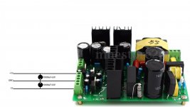
Attached my PSU with the way I expect the caps to be wired.
Attached my PSU with the way I expect the caps to be wired.
Attachments
I have a similar power supply that uses that plastic packaged "brain box". These aren't regulated supplies, so more capacitance on the output should be ok. That said, I would use multiple smaller low-ESR caps instead of a single 10,000uF standard cap per rail.
I just had a chat with Anders who recently upgrade my BMC-2 DAC. The XLR outputs are not true balanced outputs.
They don't need to be 'true' (i.e. floating) balanced outputs to make it work. Even if they're just complementary phases you can do it, just don't short the unused phase to 0V.
Also a SMPS probably won't be happy on startup with 10000uF capacitance.
I've never met one that hasn't started up with that low a capacitance on the rails. Often I'm more than 10X that and haven't had problems, I do normally use a series L though in an attempt to ward off instability.
It's come to my attention that I have to solve the bus pumping problem on my IRS2092 amp. I have 4 x IRS2092 L15DSMD boards. 2 for each speaker in bi-amping. All 4 on 1 SMPS.
I have read that 2 solutions can be either very big capacitance after the PSU. I have 2x 63V Elna's 10000uF in my drawer. Can I use these? Its a double voltage 55V PSU. If I put one in parallel (55V+ to GND and 55V- to GND) on each rail would this not create a short?
The other solution is phase inversion? What is the easiest way to invert the phase on the 2 left channel boards? My DAC actually has balanced output converted to phono? Does this make phase inversion easier if I put XLR inputs in my amp chassis (drawings pleeeease....)
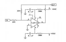
A phase inverter is not that difficult to make , see http://www.diyaudio.com/forums/clas...-irs2092-irfi4020h-200w8r-38.html#post2951879 only 4 resistors and an opamp and some decouplimg .
Put it on a piece of breadboard and your done .
Cheers ,
Rens
I found the only time I got bus pumping was with a low frequency signal on the input from a sig gen. In normal use the amp worked fine.
If you use class d in bridged mode bus pumping doesn't occur.,
If you use class d in bridged mode bus pumping doesn't occur.,
A phase inverter is not that difficult to make , see http://www.diyaudio.com/forums/clas...-irs2092-irfi4020h-200w8r-38.html#post2951879 only 4 resistors and an opamp and some decouplimg .
Put it on a piece of breadboard and your done .
Cheers ,
Rens
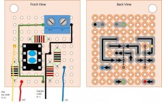
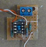
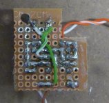
And for anyone who's interested, here's a schematic, breadboard board layout and finished product (this was the protoype - bit untidy, but it worked fine!), using Rens' design as a starting point (thanks Rens!) - and yes, they're pretty easy to make. In the back view layout, the arrows show how the component leads can be used to make the 'tracks' between the copper circles. In the photos, the brown / white wire are +/-5V, the orange/white are output, with the solid colours +ve.
Cheers,
Jon.
Attachments
Last edited:
They don't need to be 'true' (i.e. floating) balanced outputs to make it work. Even if they're just complementary phases you can do it, just don't short the unused phase to 0V.
I've never met one that hasn't started up with that low a capacitance on the rails. Often I'm more than 10X that and haven't had problems, I do normally use a series L though in an attempt to ward off instability.
Still trying to figure out if my BMC-2 DAC can phase invert, even though it is not truly balanced.
Will add capacitance at first, and try it out, with a multimeter attached. Trying to steer away from the phase inverter breadboard, as this requires modding on the amplifier PCB, and mine is L15DSMD. I've only seen guides for the regular L15D...
But thank you Sefaris. You made it look pretty basic.
Attachments

Morten, your drawing in post 6 is incorrect. You need to connect the negative pole of the bottom capacitor to the negative rail, not to GND.
/U.
/U.
Morten, your drawing in post 6 is incorrect. You need to connect the negative pole of the bottom capacitor to the negative rail, not to GND.
/U.
Oh. Thanks. Then I need capacitors above 110V.....
Trying to steer away from the phase inverter breadboard, as this requires modding on the amplifier PCB, and mine is L15DSMD. I've only seen guides for the regular L15D...
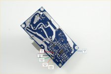
Not so much modding, more adding to - just taking the +/-5V supply off the zeners, and connecting inverter output to L15D input, as per attached pic (enlarge to see conenction points). But if you can invert at the DAC, that would be easier of course. 🙂
Attachments

It's not possible to invert at the DAC :-(
Yeah, 5V from the zeners, but I saw I had to cut a GND trace?
Yeah, 5V from the zeners, but I saw I had to cut a GND trace?
It's not possible to invert at the DAC :-(
Yeah, 5V from the zeners, but I saw I had to cut a GND trace?
Not the way I did it (and it isn't a GND trace!).
Doctordata's design continues to use the input connector on the L15D board but reroutes it to the inverter and then back to the L15D board, by cutting the Input+ (not GND) trace, and soldering the inverter input+ wire to one side of the cut and the inverter output+ to the other side. The inverter is mounted on the back of the L15D board (with some double-sided tape I think).
I did it differently - I de-soldered the input connector from the L15D board and moved it to the inverter board instead, and then just soldered the inverter output wires to where the connector used to be on the L15D board. So no need to cut any traces. I mounted the inverter board on the front of the L15D board, using a long standoff.
Both designs have exactly the same result, just different implementations - the inverter sits between the signal input and the L15D input.
The reason I did it differently was because I was mounting the L15D boards back-to-back so the inverter boards needed to be on the front rather than the back of the L15D boards. And they would need to be be mounted over the input connector, making it difficult to access to connect the signal inputs. Moving the input connector to the inverter board solved that problem and simplified the connections a bit.
But if you want to do use the trace-cut approach on the SMD boards, the attached picture might help (this time I've used the same colurs for the labels as the wires in my breadboard layouts, to help avoid confusion).
Attachments
No, 63V is correct, but the capacitor on the negative rail should have + to GND and - to -55V.
Oh so I got something right. Still makes no sense to me why the "+" on the capacitor needs to go to GND.... Wish I knew more about DC.
Not the way I did it (and it isn't a GND trace!).
Doctordata's design continues to use the input connector on the L15D board but reroutes it to the inverter and then back to the L15D board, by cutting the Input+ (not GND) trace, and soldering the inverter input+ wire to one side of the cut and the inverter output+ to the other side. The inverter is mounted on the back of the L15D board (with some double-sided tape I think).
The reason I did it differently was because I was mounting the L15D boards back-to-back so the inverter boards needed to be on the front rather than the back of the L15D boards. And they would need to be be mounted over the input connector, making it difficult to access to connect the signal inputs. Moving the input connector to the inverter board solved that problem and simplified the connections a bit.
But if you want to do use the trace-cut approach on the SMD boards, the attached picture might help (this time I've used the same colurs for the labels as the wires in my breadboard layouts, to help avoid confusion).
I will definitely not cut traces on the amplifier board if I do not have to. Am I right to assume it is only necessary building one board supplying two amps?
I will definitely not cut traces on the amplifier board if I do not have to.
I cut traces by scoring through them with a sharp object, leaving a gap of around 1mm or less. Then it's easy to reconnect them if needed, - just scratch off some of the enamel coating either side of the gap to expose the copper trace and put a solder blob across where you've cut.
Am I right to assume it is only necessary building one board supplying two amps?
Interesting question. I'm assuming you mean that you'd take the output from the one inverter and feed it to the inputs of the two L15D boards for either the left or light bi-amped channel?
The other way of doing it would be to use two inverters and feed the DAC's left or right channel output to two inverters and then on to the respective L15D boards.
Sorry, I don't know which would be better or whether there would be any problems with either approach. Maybe someone else knows and can advise?
- Home
- Amplifiers
- Class D
- Bus pumping