well no acknowledgment for spotting the potential problem nor my apology... sometimes i think trying to help is just not worth it.
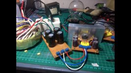
Here is the update, i build 2nd amps with brand new parts & pcb & with L now! 😀, new toroidal transformer & make dcv to 25-0-25 (18ac), using 75watt lightbulb, it dont light (barely light at first contact), the output still showing leaking voltage (20 volt), and the right cap warming up (same like first amp but dont blow). I also removing 2 4700uf & little 2 220nf at power board,
Is that normal when there is voltage at the output ? Thanks
Best.
Bobby
Is that normal when there is voltage at the output ? Thanks
Best.
Bobby
Attachments
Last edited:
Can we get a picture of board from bottom?Here is the update, i build 2nd amps with brand new parts & pcb & with L now! 😀, new toroidal transformer & make dcv to 25-0-25 (18ac), using 75watt lightbulb, it dont light (barely light at first contact), the output still showing leaking voltage (20 volt), and the right cap warming up (same like first amp but dont blow). I also removing 2 4700uf & little 2 220nf at power board,
Is that normal when there is voltage at the output ? Thanks
Best.
Bobby
A capacitor getting warm / hot / exploding is usually caused by reverse voltage, over voltage - or in truly extreme cases too much ripple current. Ripple current will NOT be the cause here...
I think it would be helpful to see some voltage measurements across the capacitors.
- ve of meter to the amplifier ground
+ve of meter to each of the positive and negative rails
DC and AC voltages would be useful to see.
I think it would be helpful to see some voltage measurements across the capacitors.
- ve of meter to the amplifier ground
+ve of meter to each of the positive and negative rails
DC and AC voltages would be useful to see.
band the right cap warming up (same like first amp but dont blow).
Do this:
Measure the DC voltage across the cap that is getting warm.
1/ What is the DC voltage as measured directly across the cap ?
2/ Does the voltage polarity appear correct ?
--------------------------------------------------------------------------------
Totally mad ridiculous thought.
Could the power board be faulty (caps open circuit) and could the voltage at the negative output of the board be AC and not DC ? dues to a faulty or incorrectly fitted bridge rectifier.
Sufficient current to overheat a big electrolytic indicates a big current.
A big current will turn on the bulb.
A big current will turn on the bulb.
Do this:
Measure the DC voltage across the cap that is getting warm.
1/ What is the DC voltage as measured directly across the cap ?
2/ Does the voltage polarity appear correct ?
--------------------------------------------------------------------------------
Totally mad ridiculous thought.
Could the power board be faulty (caps open circuit) and could the voltage at the negative output of the board be AC and not DC ? dues to a faulty or incorrectly fitted bridge rectifier.
A capacitor getting warm / hot / exploding is usually caused by reverse voltage, over voltage - or in truly extreme cases too much ripple current. Ripple current will NOT be the cause here...
I think it would be helpful to see some voltage measurements across the capacitors.
- ve of meter to the amplifier ground
+ve of meter to each of the positive and negative rails
DC and AC voltages would be useful to see.
Will do when im back home sir
Is there insulation of lm's from heatsink?
I uaing thin mica & computer cpu thermal paste sir
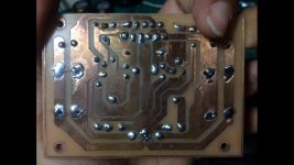
Can we get a picture of board from bottom?
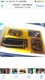
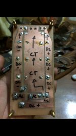
Sorry for bad image im using mobile phone for upload, im using permanent marker for this, not a clean track but there is no short circuit, i test all this board before placing the parts
Attachments
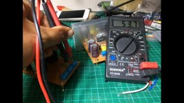
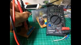
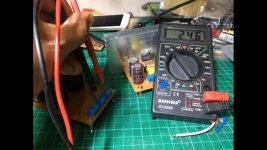
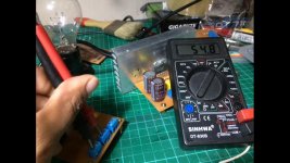
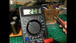
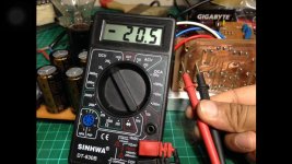
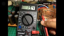
Hi everyone, i think i Found the problem here, i think im placing a BAD rectifier bridge, or it me who wrong connecting it, at output power unit there is normal -24 & +24 DC, when im change the meter to AC, the negative output ahowing 0, and i got 53VAC at CT to positive, and 107vac at negative to positive, is that normal that AC flowing into the amps ?? Should i replace the rectifier ??
Or i should try another meter ?? I got this ugly meter only for -+$3 including the 9volt battery!, and it measure thing! 😀
Or i should try another meter ?? I got this ugly meter only for -+$3 including the 9volt battery!, and it measure thing! 😀
Attachments


Last edited:
Your boards look OK.
The real test you must do is what I mentioned above. Voltage and polarity. Those two things are the only realistic problem areas.
The real test you must do is what I mentioned above. Voltage and polarity. Those two things are the only realistic problem areas.
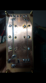
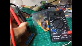
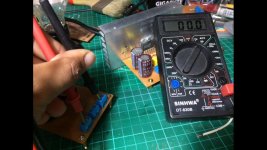
Do the test in your last three pictures again but this time swap the meter leads over.
Some meters give unpredictable results when measuring AC in the presence of DC.
Some meters give unpredictable results when measuring AC in the presence of DC.
Your boards look OK.
The real test you must do is what I mentioned above. Voltage and polarity. Those two things are the only realistic problem areas.
With cap installed or without caps sir ? Im afraid to connect it because its instantly heated up, 5sec i connect it and the heat like iron, smells bad when it explode
It was really with caps fitted. That's why I mentioned soldering wires to the caps and connecting to your meter first. Then you can quickly switch on and off and get a reading.
It is a very strange problem.
It is a very strange problem.
Do the test in your last three pictures again but this time swap the meter leads over.
Some meters give unpredictable results when measuring AC in the presence of DC.
Did you try this ?
Attachments

Last edited:
If you connect the power supply voltage as in first picture you have connect a 54v A.C to the right capacitor,burned capacitor and the magic smoke come!
You must measure 0v A.C here.
You must measure 0v A.C here.
Last edited:
BPS,
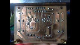
pls mark the connection (+/-ac, ac) of the rectifier on the power supply board on the bottom side and check that the transformer is really centertapped and connected correct to the power supply board.
BR
Gunni
pls mark the connection (+/-ac, ac) of the rectifier on the power supply board on the bottom side and check that the transformer is really centertapped and connected correct to the power supply board.
BR
Gunni
There you go sir
That's great, thanks. Those results are a mirror image of the first readings and so seem to confirm its a meter reading anomaly.
-------------------------------------------------------------------------------------
If I look at the picture in post #22 then the positive mark on the four caps are all on the right hand side.
Your DC voltage measurements seem to be of the correct polarity and agree with the cap positions in post #22.
And is the cap getting hot now ? with those voltage readings.
Working from pictures isn't easy 🙂 Can someone confirm this.
In post #22 the red positive output wire from the power PCB appears to go to the left hand side (the negative) of the caps on the amp board.
In post #22 the red positive output wire from the power PCB appears to go to the left hand side (the negative) of the caps on the amp board.
BPS,
pls mark the connection (+/-ac, ac) of the rectifier on the power supply board on the bottom side and check that the transformer is really centertapped and connected correct to the power supply board.
BR
Gunni
Here you go sir
That's great, thanks. Those results are a mirror image of the first readings and so seem to confirm its a meter reading anomaly.
-------------------------------------------------------------------------------------
If I look at the picture in post #22 then the positive mark on the four caps are all on the right hand side.
Your DC voltage measurements seem to be of the correct polarity and agree with the cap positions in post #22.
And is the cap getting hot now ? with those voltage readings.
They still getting hot sir and still have -+20 vdc at the speaker output sir
Working from pictures isn't easy 🙂 Can someone confirm this.
In post #22 the red positive output wire from the power PCB appears to go to the left hand side (the negative) of the caps on the amp board.
It is in right direction sir, pls have a look picture at #1 post
Or I just simply surrender it and swap the amp layout with battle proven layout ? 😕
Attachments
Last edited:
- Status
- Not open for further replies.
- Home
- Amplifiers
- Chip Amps
- My first amp & its blown (need help)