Hi Folks.
long time lurker.
I have a 0.5 cubic feet pre made cabinet.
I want to make a small studio monitor for listening distance of about 1 meter.
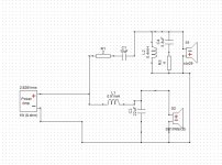
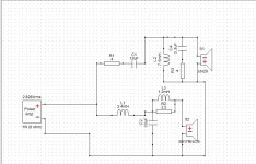
going to use SB17CRC35-4 midwoofer and SB29RDNC-C000-4 tweeter.
being playing around with the crossover settings using the factory response files.
this is my first crossover design so any input is appreciated.
one question,
How do i add the cabinet response to the crossover design?
i also have a measuring microphone,oscilloscope and tone generator on my pc...


long time lurker.
I have a 0.5 cubic feet pre made cabinet.
I want to make a small studio monitor for listening distance of about 1 meter.
going to use SB17CRC35-4 midwoofer and SB29RDNC-C000-4 tweeter.
being playing around with the crossover settings using the factory response files.
this is my first crossover design so any input is appreciated.
one question,
How do i add the cabinet response to the crossover design?
i also have a measuring microphone,oscilloscope and tone generator on my pc...
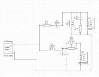
Attachments
-
 crossover_ver2.jpg159.2 KB · Views: 2,219
 -
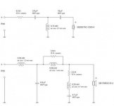
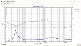
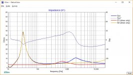 crossover_IMP_ver2.jpg155 KB · Views: 2,050
 -
SB29RDNC-C000-4.zma.txt5.3 KB · Views: 184
-
SB29RDNC-C000-4.frd.txt4.6 KB · Views: 173
-
SB17CRC35-04.zma.txt6.8 KB · Views: 155
-
SB17CRC35-04good.frd.txt8.9 KB · Views: 161
-
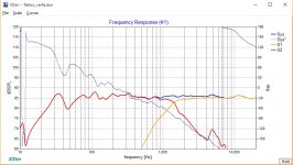
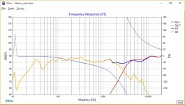
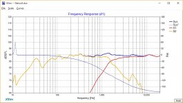 crossover_FR_ver2.jpg162.5 KB · Views: 2,252
Hi TheBrain!
Nice job so far! As for your questions: Don't simulate, measure. 🙂 You have already proven more or less the compatibility of your drivers.
Since this is a 2-way with relatively high crossover point, I would go ahead and put the drivers in the cabinet and measure using gated-far field at 1m and then do all of my crossover simulation from that, without using any more data-massaging techniques. If this was a 3-way involving much lower xover points this advice would no longer be valid.
Also, measure the speaker in place. That is, if you plan for this to be a near-wall or desktop, you should take your measurements there. If you plan on being stand-mounts in free space, measure from that.
This goes very much against the grain of doing everything quasi-anechoic, but it's much simpler and will yield a more tailor-made solution. Why fix baffle step if you don't have to? 🙂
If on the other hand, simulation is your thing, search Google for "Jeff Bagby" and "Blender" as it will give you I think the additional data you are looking for.
One more thing, your sim is good, but if this was pre-production, I'd say your woofer peak is way too high. You need to tune your LP filter so that you peak around 100 Hz or lower. Also, since I do everything at 1m I use the B&K reference curves, which end up descending. YMMV. But the point is, I think you'll loose quite a bit of sensitivity before you are really done. 🙂 Once you have real measurements this can be dealt with so this is not a big concern yet.
Best,
E
Last edited:

Thank you for the input!Hi TheBrain!
Nice job so far! As for your questions: Don't simulate, measure. 🙂 You have already proven more or less the compatibility of your drivers.
Since this is a 2-way with relatively high crossover point, I would go ahead and put the drivers in the cabinet and measure using gated-far field at 1m and then do all of my crossover simulation from that, without using any more data-massaging techniques. If this was a 3-way involving much lower xover points this advice would no longer be valid.
Also, measure the speaker in place. That is, if you plan for this to be a near-wall or desktop, you should take your measurements there. If you plan on being stand-mounts in free space, measure from that.
This goes very much against the grain of doing everything quasi-anechoic, but it's much simpler and will yield a more tailor-made solution. Why fix baffle step if you don't have to? 🙂
If on the other hand, simulation is your thing, search Google for "Jeff Bagby" and "Blender" as it will give you I think the additional data you are looking for.
is there a tutorial on how to calibrate the test setup?
there are some programs that do it like ARTA "Steps" but the instructions for calibrating the system are not good.
I really want to get around the measuring procedure.
also this way i can post the FR of the finished speaker🙂
One more thing, your sim is good, but if this was pre-production, I'd say your woofer peak is way too high. You need to tune your LP filter so that you peak around 100 Hz or lower. Also, since I do everything at 1m I use the B&K reference curves, which end up descending. YMMV. But the point is, I think you'll loose quite a bit of sensitivity before you are really done. 🙂 Once you have real measurements this can be dealt with so this is not a big concern yet.
Best,
E
did you mean 1000 Hz?
there is a peak in the crossover point there.
i also noticed it.also there is a dip in around 130 HZ.
I dno't know about Arta, but others do. I would not try to "get around" the measurement at all! It's the most important part of the design process. Everything else revolves around it. I personally use OmniMic + DATS but I think ARTA and Room EQ Wizard are popular choices.
Actually, your woofer is shaped like a hay stack. Instead you should shoot for it to peak from 40-100 Hz, and go flat or descend. This is tuned like a boom box / cheap car speaker. 🙂
Best,
E
Actually, your woofer is shaped like a hay stack. Instead you should shoot for it to peak from 40-100 Hz, and go flat or descend. This is tuned like a boom box / cheap car speaker. 🙂
Best,
E
Also, remember you will need FR, Z AND the driver offset before you can correctly simulate your speaker in XSim (and most any other such tool)
I dno't know about Arta, but others do. I would not try to "get around" the measurement at all! It's the most important part of the design process. Everything else revolves around it. I personally use OmniMic + DATS but I think ARTA and Room EQ Wizard are popular choices.
Actually, your woofer is shaped like a hay stack. Instead you should shoot for it to peak from 40-100 Hz, and go flat or descend. This is tuned like a boom box / cheap car speaker. 🙂
Best,
E
here is where the language differences come to play🙂
"get around" in my native language actually means understanding it better.
I want to learn how to do it properly.
Also, remember you will need FR, Z AND the driver offset before you can correctly simulate your speaker in XSim (and most any other such tool)
you did mean 100 Hz.
took your advice played with it a bit more, and added a notch filter:
Attachments

Visit Charlie's Audio Pages and you should find a tutorial and different software suited to your needs ( Response Modeler or FRD Response Blender, both Excel spreadsheets).
Visit Charlie's Audio Pages and you should find a tutorial and different software suited to your needs ( Response Modeler or FRD Response Blender, both Excel spreadsheets).
Thank You!
Yep, your second try looks a lot better!
Tip: You can use the ground symbol to minimize wiring and re-wiring. 🙂
Best,
E
Tip: You can use the ground symbol to minimize wiring and re-wiring. 🙂
Best,
E
Yep, your second try looks a lot better!
yessss

thanks to you
Tip: You can use the ground symbol to minimize wiring and re-wiring. 🙂
Best,
E
from all the excitement of editing the crossover i didn't even think about it
It looks like you don't have any phase info for your drivers, and that will affect the actual response quite a bit. For the drivers, you can use "derived" phase (see the checkbox in the drivers' tune window), though there will of course be an unknown time offset. If you know where the pole piece of the drivers is, you can usually estimate the driver offset from that and include it to get closer.
It looks like there's no phase data for the impedance, either. I never got around to fixing the "derived phase" for impedances in Xsim (some problems came up, I forget what now). But you really do need to know the complex impedances of the drivers to get the response correct, also. Something like WooferTester2 or DATS are a nice convenient (though not free) way to get that if the manufacturer (as usual) doesn't supply it.
It looks like there's no phase data for the impedance, either. I never got around to fixing the "derived phase" for impedances in Xsim (some problems came up, I forget what now). But you really do need to know the complex impedances of the drivers to get the response correct, also. Something like WooferTester2 or DATS are a nice convenient (though not free) way to get that if the manufacturer (as usual) doesn't supply it.
It looks like you don't have any phase info for your drivers, and that will affect the actual response quite a bit. For the drivers, you can use "derived" phase (see the checkbox in the drivers' tune window), though there will of course be an unknown time offset. If you know where the pole piece of the drivers is, you can usually estimate the driver offset from that and include it to get closer.
It looks like there's no phase data for the impedance, either. I never got around to fixing the "derived phase" for impedances in Xsim (some problems came up, I forget what now). But you really do need to know the complex impedances of the drivers to get the response correct, also. Something like WooferTester2 or DATS are a nice convenient (though not free) way to get that if the manufacturer (as usual) doesn't supply it.
Thanks bwaslo.
i'll do that.
oh i just realized you are the one that made xsim 🙂
a job well done!!

honestly it is the most friendly and intuitive tool for designing the crossover i used.
when the drivers get here i will try to measure them properly in the box.
I wasn't worried about the phase data as I thought this was just a trial run. 🙂 He's right though.
When you actually start measuring in place all that will matter.
Best,
E
When you actually start measuring in place all that will matter.
Best,
E
This comes without recommendation, but this is a couple of variants on SB Acoustics EKA kit, which is about 18L. 340h X 200w X 330d.
They use 6" SB17NRXC35-4
6" SB17NRXC35-4 :: SB Acoustics
You've got a 6" SB17CRC35-4
6" SB17CRC35-4 :: SB Acoustics
They don't look wildly different to me. The CRC is a tidge deeper bass Fs. Heavier cone. Your SB29RDNC tweeter is about 2dB louder than the one in the EKA, which shouldn't be hard to adjust.
SB26STAC-C000-4 :: SB Acoustics
SB29RDNC-C000-4 :: SB Acoustics
So bottom line, both crossovers ought to be pretty competent, but of course the bass tuning would be different. I'd guess they are about 3kHz crossover. So a point of departure at least. The second one adds a notch to the 5kHz breakup. But you sure can't cross at 800Hz!
Attachments
This comes without recommendation, but this is a couple of variants on SB Acoustics EKA kit, which is about 18L. 340h X 200w X 330d.
They use 6" SB17NRXC35-4
6" SB17NRXC35-4 :: SB Acoustics
You've got a 6" SB17CRC35-4
6" SB17CRC35-4 :: SB Acoustics
They don't look wildly different to me. The CRC is a tidge deeper bass Fs. Heavier cone. Your SB29RDNC tweeter is about 2dB louder than the one in the EKA, which shouldn't be hard to adjust.
SB26STAC-C000-4 :: SB Acoustics
SB29RDNC-C000-4 :: SB Acoustics
So bottom line, both crossovers ought to be pretty competent, but of course the bass tuning would be different. I'd guess they are about 3kHz crossover. So a point of departure at least. The second one adds a notch to the 5kHz breakup. But you sure can't cross at 800Hz!
wow😱
i didn't even pay attention to my crossover point at the second try!
probably was blinded by the theoretical overall response.
Thank you for that!
i will simulate both designs with the responses from SB17CRC35-4 & SB29RDNC-C000-4
it's a good place to start from.
tired the crossover you recommended(SB Acoustics EKA kit).
it sort of works but maybe for a more HiFi pleasing sound.
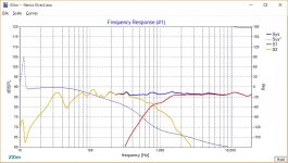
I'm aiming for the flattest response i can get.
here is the FR of the EKA crossover with my drivers:

and here is another try with a sane cross point😉


it sort of works but maybe for a more HiFi pleasing sound.
I'm aiming for the flattest response i can get.
here is the FR of the EKA crossover with my drivers:
and here is another try with a sane cross point😉
Attachments
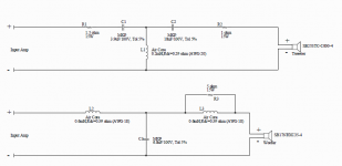
DISCUSSION TOPIC: Tweeter attenuation L-pad, vs. series attenuation resistor from amplifier vs. weighted combination of both.
Since the impedance of this midbass is close to 4-ohms, using an L-pad on the Re=3.8 ohm tweeter does not put additional stress on the amplifier. The ground-shunt resistor on a tweeter L-pad typically reduces the range of tweeter Z-variation, and this produces a more ideal electrical crossover shape. Only baffle simulations/measuments will determine if the L-pad also produces a better acoustic crossover shape than a series attenuation resistor -or- if some combination of both circuits performs best.
If the midbass impedance was higher(6-8ohms), then using a series attenuation resistor from the amp to the start of the tweeter crossover circuit to increase the total tweeter impedance closer to the midbass is common. Again, combining some attenuation from the L-pad with some attenuation-tuning from the amplifier intput series resistor is common.
Fun stuff.... but don't buy parts until you have in-cabinet, in place measurements. 🙂
Best,
E
 will do.
tried my first measuring yesterday.
still having problems calibrating the system correctly.
will dive into it more in the weekend.
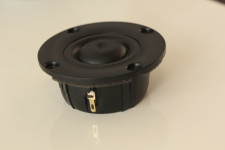
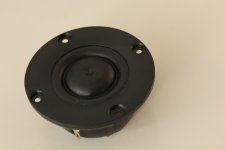
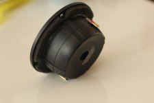
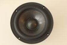
Finally the drivers have arrived!
Our post service has gone really bad in the last years.
took them 3 weeks to deliver the package which was already cleared from customs [/rant]
In this time i've gone greedy and decided i'm going to make this project a 3 way midfield.
what woofer should i use for the low frequency? sb acoustics? morel? 10"? 12"? active xo? passive xo? cabinet size? decisions decisions 🙂
tomorrow i'm going to do the measurements in the. 0.5 cubic ft. cabinet for practice.
in the meanwhile some speaker porn:


Our post service has gone really bad in the last years.
took them 3 weeks to deliver the package which was already cleared from customs
[/rant]In this time i've gone greedy and decided i'm going to make this project a 3 way midfield.
what woofer should i use for the low frequency? sb acoustics? morel? 10"? 12"? active xo? passive xo? cabinet size? decisions decisions 🙂
tomorrow i'm going to do the measurements in the. 0.5 cubic ft. cabinet for practice.
in the meanwhile some speaker porn:
Attachments
- Status
- Not open for further replies.
- Home
- Loudspeakers
- Multi-Way
- Small studio monitor using SB Acoustics SB17CRC35-4 and SB29RDNC-C000-4