Thanks Juanhello nguyen
check the trim pot maybe is either the value or one of the leads is not bypassed by the other one leads or, maybe one of the resistors that is on the area of the bias circuits the value might be too high "check trim first" the trim can be 500ohms 🙂
this image show annotations from Carlos
Best Regards
Juan
I'm sure that trimpot use is 500ohm, now the sound it good but transistor 3281/1302 just warm, not hot. Maybe I untapped possibilities of cỉcuit. If set bias ok, i think it sound will is hi-end.
Did you test the tracks of the circuit board before soldering the components?
a micro cut invisible to the eye is possible.
a micro cut invisible to the eye is possible.
hi All
I have finished DX super A, after change resistor R4, C37, R32,R14, I 've adjusted 250mA, Transistor hot in 50oC, good sound.
Next project, pls help me share layout irron file DX super A with 2 pair Sanken, im find all topic but not found.
Thank so much.
I have finished DX super A, after change resistor R4, C37, R32,R14, I 've adjusted 250mA, Transistor hot in 50oC, good sound.
Next project, pls help me share layout irron file DX super A with 2 pair Sanken, im find all topic but not found.
Thank so much.
Very happy i am, prototype pcboard from DxS project gonna arrive today
Yeeeessssss!
I will read thread soon, now too much happy, gonna dance!🙂🙂🙂
Instigating, provokating video already uploaded...asking competition if they are afraid...if not...they should!.... their amplifiers, when compared with this one will result, their ones, in piece of junk.
https://www.youtube.com/watch?v=OD7LoZ0O9ec
Sounds the same as Dx Super A, a little bit more treble and more dinamics...waveform going perfect till 50 Kilohertz when Super A starts to be ugly at 30 Khz...distortion is less than 0.000229% THD.
Will think if i gonna publish...maybe yes...maybe not.....i do not know.
regards,
Carlos
Attachments
I am busy again...having fun building things.
I will see you early future...gonna make videos of my constructions.
It cost me a fortune to produce two prototype pcboards for testing purpose.... a lot of money.
regards,
Carlos
I will see you early future...gonna make videos of my constructions.
It cost me a fortune to produce two prototype pcboards for testing purpose.... a lot of money.
regards,
Carlos
Attachments

Dx Super A, 1 kilowatt minimum to a stereo set
Small modifications, 80 volts supplies...just that.
https://www.youtube.com/watch?v=adrlFapHoDg
regards,
Carlos
Small modifications, 80 volts supplies...just that.
https://www.youtube.com/watch?v=adrlFapHoDg
regards,
Carlos
Dear Sir.............
Thanks a lot.........
DX super A is superb...........
You are really great.............
A great source of inspiration for people like me.
I couldn't study electrrnics during my graduation, but its my passion. So I learned by experimenting and following the words and circuits designed by great people like you.
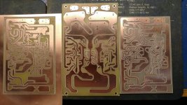
I made PCB from Mr. Zimmer's layout by toner transfer.....
Pls see the pics....
I wish to use this to drive my sub-woofer.
Thank you once again,
Thanks a lot.........
DX super A is superb...........
You are really great.............
A great source of inspiration for people like me.
I couldn't study electrrnics during my graduation, but its my passion. So I learned by experimenting and following the words and circuits designed by great people like you.
I made PCB from Mr. Zimmer's layout by toner transfer.....
Pls see the pics....
I wish to use this to drive my sub-woofer.
Thank you once again,
You are welcome Sumeshak....please upload pictures to my email again
I have lost the first time you sent.
Down this post, in the signature line you can see Zimmer testing DxS MKII, the ultimate model.
regards,
Carlos
I have lost the first time you sent.
Down this post, in the signature line you can see Zimmer testing DxS MKII, the ultimate model.
regards,
Carlos
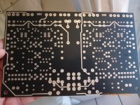
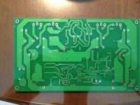
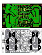
My DX SuperA PCB
I have made my own layout for my large capacitors. The placement is referenced from the 2015 blue PCB version.
I have made my own layout for my large capacitors. The placement is referenced from the 2015 blue PCB version.
Attachments

Last edited:
I have made my own layout for my large capacitors. The placement is referenced from the 2015 blue PCB version.
that looks nice sir I see you are going to use special type caps I can wait to see it populated with parts, thumps up sir 🙂 and good luck I hope all goes smoothly on your build
Best Regards
Juan
I have made my own layout for my large capacitors. The placement is referenced from the 2015 blue PCB version.
Could you please share me your layout files please¡¡¡
regards wolfintosh
Hi
Thanks for you guys appreciation~ But I have not had the board tested for sharing. I will surely share it later. My board was ordered from China Taobao.
And I wanna get Carlos's approval for distribution in Hong Kong region later.
Thanks for you guys appreciation~ But I have not had the board tested for sharing. I will surely share it later. My board was ordered from China Taobao.
And I wanna get Carlos's approval for distribution in Hong Kong region later.
I want you to share all files needed for DIY forum guys to assemble
and etch by themselves.
You can distrubute in earth and even into planet mars if you obbey some rules.
You are authorized to use the audio amplifier schematic to produce group buys.... and should do it.
Also you can distribute and sell but do not have huge profit, maximum 30 percent.
Must say the circuit is deeply inspired into Doctor Self Blameless.
My name, as circuit designer, must be keept and printed into the circuit board, the pcboard must be assembled and tested prior to produce to distribute in foruns or elsewere.....this is a DIY design that should be shared.
So, black and white layout for etching, in photo methods or hot iron method should be offered after tests to our community....if people prefer to buy pcboard from group buy or elsewere i cannot see a problem, but keep the forum rules....here is not a market place...if you want to distribute here, then go to group buy section and be aware you cannot have profit, just calculate your costs to produce prototype and other small costs that should be considered and share (inside the price) to the ones gonna order...i repeat..real profit is NOT allowable here.
Also i want all gerber files used to produce the pcboard together your written authorization to use it to produce and distribute in Brazil if i decide to do it (probably i will not do it...but it is a rule)
I want a sample to me to build and to be sure nothing wrong is happening within the pcboard layout...i must check myself....so...one pcboard must be shipped to me for testing purposes.... my home adress you can have it using private forum messenger.
regards,
Carlos
Last edited:
i would love to have them for iron method after testing, and i would deeply apricciate it, thanks a ton hajame and uncle CharlieHi
Thanks for you guys appreciation~ But I have not had the board tested for sharing. I will surely share it later. My board was ordered from China Taobao.
And I wanna get Carlos's approval for distribution in Hong Kong region later.
Notice of Intent to build
Hi All I have been reading these threads for the last few days
and made a layout based on the last work shown. I have homemade CNC's and so needed Gerbers as I am not good at etching, also its much nicer drilling with CNC.
Mostly I have been building Headphone amps but the large amount of documentation here makes this one interesting, and so I accept the challenge.
Except for the large transistors, have most of the parts here.
A big thanks to all who helped on these amps.
I will not complain if my layout does not perfom
Attachments

Last edited:
hi
any one here build the SUPER A ..
1- the heat sink gets very hot with the 10R resistor in place of the fuse(voltage drop is 2.3v?
2- when the voltage drop on that resistors is much less (about 0.5v or less ) the is running very smooth and cold and louder ... but it damages the test speaker?
3-the ac output voltage is less than 10v while playing tracks but when tested with ARTA software producing 1000hz sine wave the output is 30vac?
can any one clears that ?
Thank you
hi
any one here build the SUPER A ..
1- the heat sink gets very hot with the 10R resistor in place of the fuse(voltage drop is 2.3v?
2- when the voltage drop on that resistors is much less (about 0.5v or less ) the is running very smooth and cold and louder ... but it damages the test speaker?
3-the ac output voltage is less than 10v while playing tracks but when tested with ARTA software producing 1000hz sine wave the output is 30vac?
can any one clears that ?
Thank you
i did build pieces of super a . it is harder to bias than mk2 but i loved the sound . super a is a class ab amp if you want a cold amp build class d at the expense of sound defination regards stewin
- Home
- Amplifiers
- Solid State
- Dx Blame ST together Dx Super A