I have been looking at the triode cascode circuit as a phono preamp first stage as many have done. I see the advantages as high gain, low input capacitance,and relatively low noise.
To get a feel for the circuit I like to run spice simulations which I did in this case. I simulated for circuits using 12AU7, 6N1P, and 12AX7 using various biasing schemes.The difference in gain was about 9dB with the 12AX7 giving the highest gain (expected higher Gm tubes to have given the higher gain).
I also looked at the FFT knowing of course that the results would be of limited accuracy. Interestingly the distortion spectrum was amazingly consistent regardless of which tube was used or the bias points. HD2 was very low -60 to -80dB but HD3 was always between -36dB and -39dB. I kind of expected HD3 to dominate but was surprised that it was that high and that consistent.
So three questions for those who have designed cascodes.
1. Is the HD3 really this high (or the relative differences between HD2 and HD3).
2. Are there any design considerations that can be used to minimize HD3?
3. How objectionable is the HD3 in real life.
mike
...HD3 was always between -36dB and -39dB.
Seems too high distortion at signal levels present in phono input.
What signal level did you use in simulations ?
Cascoded Triodes gives much better real-world performance than text-books suggest, and simulations are certainly not very reliable.
I started work on series cascodes over 12 years ago, and found that the important consideration is the cascode voltage. Using a triode at the top gives poor results compared to higher-gm devices, and bipolar transistors measure and sound the best.
Turning from Series to Shunt cascode improves performance again, and the gain can be increased greatly, without having to resort to high voltages.
It makes a superb RIAA EQ stage, because the output is a current, and so you only need a shunt-connected EQ network. this in turn means that the EQ performance does not get corrupted by the ra of the triode.
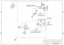
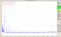
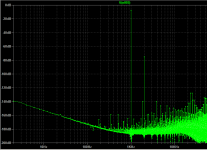
Here's an outline drawing of a 6Э5П shunt cascode, and a real measurement of spectrum at an output voltage of 1kHz, 75V peak-peak. No sign of 3rd harmonic problems at all!
The stage gain is about 170.
I started work on series cascodes over 12 years ago, and found that the important consideration is the cascode voltage. Using a triode at the top gives poor results compared to higher-gm devices, and bipolar transistors measure and sound the best.
Turning from Series to Shunt cascode improves performance again, and the gain can be increased greatly, without having to resort to high voltages.
It makes a superb RIAA EQ stage, because the output is a current, and so you only need a shunt-connected EQ network. this in turn means that the EQ performance does not get corrupted by the ra of the triode.
Here's an outline drawing of a 6Э5П shunt cascode, and a real measurement of spectrum at an output voltage of 1kHz, 75V peak-peak. No sign of 3rd harmonic problems at all!
The stage gain is about 170.
Attachments

Getting results which look wrong probably means they are wrong. Something in your circuit or analysis is not right. To a first approximation, a cascode gives you the distortion from a plain triode feeding into a lowish impedance so you mainly see the nonlinearity of transconductance. Second order should dominate.mashaffer said:I also looked at the FFT knowing of course that the results would be of limited accuracy. Interestingly the distortion spectrum was amazingly consistent regardless of which tube was used or the bias points. HD2 was very low -60 to -80dB but HD3 was always between -36dB and -39dB. I kind of expected HD3 to dominate but was surprised that it was that high and that consistent.
Voltage gain is almost meaningless, as a cascode is a transconductance amplifier.
.
Voltage gain is almost meaningless, as a cascode is a transconductance amplifier.
We are talking about the practical circuit: the load resistor is included. The outcome for an amplifier is a circuit delivering voltage gain.
Voltage gain is most relevant to the circuit performance, and the measured distortion also, at least somewhat.
With a low value anode resistor R, voltage gain is gm times R. The fact that the OP did not see this means either that he used a higher resistor value, or a different one for each circuit.
With a perfect CCS load voltage gain will be around mu^2. This will require a CCS with impedance much higher than mu x anode impedance - say CCS impedance of 20-50M for a 12AX7?
Typical biasing might mean an anode resistor roughly equal to the anode impedance. This will give a voltage gain around mu. I suspect that this is roughly what he saw, but modified by the exact resistor value.
Seems too high distortion at signal levels present in phono input.
What signal level did you use in simulations ?
5mV in output was around 300mV (Both peak).
mike
Why ever would you expect H3 to dominate in a single-ended triode circuit? Listen to DF96, he's never wrong.I kind of expected HD3 to dominate
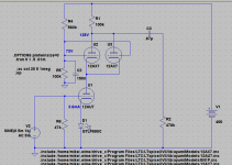
The basic circuit...
View attachment 592967
I did diddle with the load resistor some with the other tubes (esp with the 12AX7 as the current was so much lower).
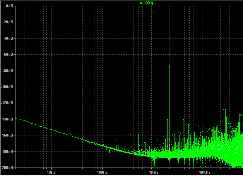
The above circuit gave this result.
View attachment 592968
View attachment 592969
View attachment 592967
I did diddle with the load resistor some with the other tubes (esp with the 12AX7 as the current was so much lower).
The above circuit gave this result.
View attachment 592968
View attachment 592969
Last edited by a moderator:
I just noticed something. The distortion appears in the input signal as well??? I am using the same directives such as plotwinsize that I have used successfully before. hmmm.
Never mind. I buggered up the trans command... better.
Never mind. I buggered up the trans command... better.
Attachments

Last edited by a moderator:
Mystery solved. Now I can play with using 12AU7 or 6N1P on the bottom and paralleled 12AX7 on top. 🙂
You are running into the limitation of a series cascode: to get the gain you require needs a high-value resistor, but the drop across that resistor demands an excessively high supply voltage.
Turning down the current in this circuit usually increases distortion.
In practice (measurement rather than simulation) all the triodes & triode-connected pentodes I have tested give low distortion at high current, and high-gm types running 14-30mA are best.
The family of Tuner triodes are designed expressly for cascode stages, and this includes the E88CC - still in production at JJ. These give good performance at low voltages, and their high gm means a lower value resistor can be used. Better to use these than the 12AU7.
No doubt you are right Rod and for a no holds barred effort I am filing away all these nuggets. The first project is a small console stereo resto-mod using what I have on hand as much as possible and I have a half dozen 6N1P and a couple dozen 12AU7 and even more 12AX7 oh, and a handful of 12AY7. I have some flexibility on the B+ so I can probably go higher than 300V.
I think that 40-45dB gain for the first stage will be adequate as there will be second stage (VAS1--Tc1--VAS2--Tc2--Buffer). However will continue to look at what I can do to improve results.
I think that 40-45dB gain for the first stage will be adequate as there will be second stage (VAS1--Tc1--VAS2--Tc2--Buffer). However will continue to look at what I can do to improve results.
I can't see your attachments. Never mind, it seems you have found your mistake.
Bear in mind that the cascode has almost no PSRR (i.e. 0dB) so it needs a very clean supply rail.
Bear in mind that the cascode has almost no PSRR (i.e. 0dB) so it needs a very clean supply rail.
I can't see your attachments. Never mind, it seems you have found your mistake.
Bear in mind that the cascode has almost no PSRR (i.e. 0dB) so it needs a very clean supply rail.
Thank you for the reminder.
Just for giggles. 400V supply Parallel 12AX7 on top 12AU7 on the bottom Gain 40dB.
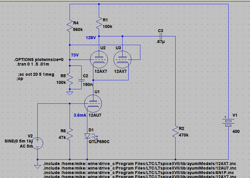
P.S. Ignore the voltage lables on the schematic they are from a previous circuit.
P.S. Ignore the voltage lables on the schematic they are from a previous circuit.
Attachments
Last edited:
Interestingly going to a single 12AX7 on top (at lower current of course) allows me to either get even higher gain (bigger load resistor) or lower B+ for same gain at the expense of higher noise and distortion no doubt. So many design trade-offs. 🙂
If I really push it to 400V with a 6N1P on the bottom and a single 12AX7 on top running about 1mA and a 240k load I can get about 47dB of gain. Of course the first time constant would have to be designed very carefully for that high of Zout and might not be worth it for a few extra dB gain. So design options seem to range between 35 and 45 dB for the initial gain stage.
If 60dB before EQ is adequate gain than even the all 12AU7 version followed by a high mu gain CC gain stage should be adequate (e.g. the original 300V B+ 12AU7 cascode followed by 12AY7 CC with 120k load on the 12AY7 gives about 65dB gain. 6N1P as second is similar but better distortion results.
If 60dB before EQ is adequate gain than even the all 12AU7 version followed by a high mu gain CC gain stage should be adequate (e.g. the original 300V B+ 12AU7 cascode followed by 12AY7 CC with 120k load on the 12AY7 gives about 65dB gain. 6N1P as second is similar but better distortion results.
Last edited:
That doesn't look healty, the AX7 has to go positive on it's grid to get the current (2x1.8mA at 60V).So one on top is even worse.
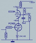
Try this one, the PC900 isn't very linear to say the least but not that terrible with the small signals from a phono cartrige.
The advantage of the PC900 is the high transconductance at relatively low current.Here 6mA and 11mA/V.Will give a gain of well over 200x.
Mona
Try this one, the PC900 isn't very linear to say the least but not that terrible with the small signals from a phono cartrige.
The advantage of the PC900 is the high transconductance at relatively low current.Here 6mA and 11mA/V.Will give a gain of well over 200x.
Mona
Attachments
- Status
- Not open for further replies.
- Home
- Amplifiers
- Tubes / Valves
- cascode distortion Spectrum.