Yes. Tempted to just try the 12AU7 version with 6N1P second VAS stage and see how it does. Right now I am working on the speaker mounting and cabinet stiffening part of the project. Then probably do the line preamp part followed by the phono pre so might be a while before the solder flies on it. 🙂
You can usually improve that by removing the 'screen grid' decoupling cap.Bear in mind that the cascode has almost no PSRR (i.e. 0dB) so it needs a very clean supply rail.
Then you would need to ensure that the upper valve takes no grid current. This will often be the case anyway, but just another example of knock-on effects when a design is changed in a 'trivial' way.
No change there. You always need to ensure there is no grid current, especially if the cap is there since it would cause bias shift / blocking distortion.Then you would need to ensure that the upper valve takes no grid current.
Blocking distortion is unlikely unless the grid current is large, as a change in upper grid voltage and hence lower anode voltage will only have a small effect on cascode behaviour unless excessive. The situation is quite different from grid current in a stage with a grounded cathode; in a cascode the upper cathode is fairly free to move. You might get intermodulation as the transconductance of the lower valve changes a bit.
Without the cap you get grid current distortion from the high resistance potential divider. Although having thought about it this might not do too much damage as the gain from the upper grid to the upper anode is quite small.
Without the cap you get grid current distortion from the high resistance potential divider. Although having thought about it this might not do too much damage as the gain from the upper grid to the upper anode is quite small.
Turning from Series to Shunt cascode improves performance again, and the gain can be increased greatly, without having to resort to high voltages.
Ho Rod, may I ask in what way is the peroformance improved by going with the shunt cascode (thought they were cald folded cascode, but perhpas that is more commonly used among the transistor folks? 🙂), are there differences in how the harmonics are shaped and if so in what directions?
TOP
Last edited:
I suspect you're speaking more from theory than practice. Drive a cascode to the point of grid current in the upper triode and you get significant bias shift (assuming typically large feed resistors) which alters the gain quite significantly, both by modulating the upper triode's rk and by wiggling the lower triode's gm (typical triode choices for cascodes being quite nonlinear ones). Guitar circuits exaggerate the effect deliberately to get compression, but it can happen in borderline hi-fi circuits too, where none at all can be tolerated obviously (blocking is just another name for bias shift when taken to the extreme; I use the term to cover a broad bit of that gain compression spectrum, not just total cutting out). Of course, this is highly unlikely in a phono front end since the signal levels are too puny to get to the point of grid current, so no one is ever likely to 'check' for it; you can just remove the unecessary cap.in a cascode the upper cathode is fairly free to move.
Last edited:
Ho Rod, may I ask in what way is the peroformance improved by going with the shunt cascode (thought they were cald folded cascode, but perhpas that is more commonly used among the transistor folks? 🙂), are there differences in how the harmonics are shaped and if so in what directions?
TOP
a few Shunt Cascode improvements:
- Easy to achieve gain of x150-250 with modest output resistor 10-33K
- Power supply rejection improved (current source in series with power supply)
- Triode's anode-current does not pass through the load resistor, so that high anode current triodes can be used, without need for high voltages.
- Can use cheap driver tubes for driving big output valves
- Can make RIAA EQ stage without series resistor, (shunt network 2R 2C)
- RIAA stage without (Bad) influence of triode's internal anode resistance.
- SIGNAL output current flows in small loop, and does not flow through PSU capacitor: output resistor grounded.
Thanks a lot Rod for your thorough listing of pros, makes sense and I even learned a few new things.
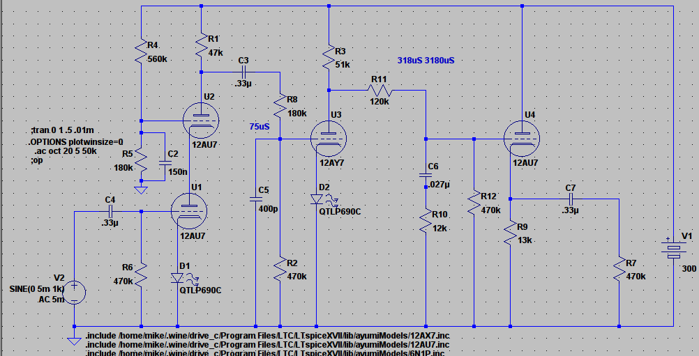
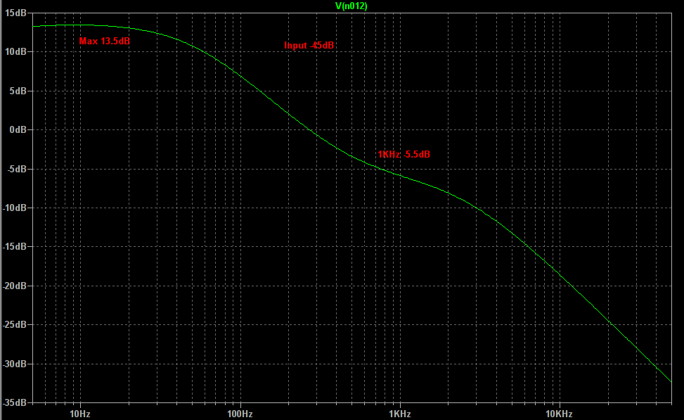
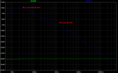
Two stage passive using all 12AX series tubes that I have on hand. Mid-band gain just shy of 40dB. Need to optimize coupling caps and the like but looks to me like it is in the ballpark.
Attachments
Listen to DF96, he's never wrong.
Since becoming a member here I have found this out. I can only strive to acquire a fraction of the knowledge that Dave provides us. Merlin you too are extremely bright and you have great articles for us noobz to learn from.
I will take this time to thank the both of you for sharing your knowledge here with us. I truly enjoy reading all of your posts!

You can remove C2 to improve PSRR (who doesn't like fewer caps!).Made a few tweaks (coupling caps and switch to cap coupled rather than direct coupled to follower). Seems to work improve gain and distortion a bit.
The basic circuit...
View attachment 592967
I did diddle with the load resistor some with the other tubes (esp with the 12AX7 as the current was so much lower).
The above circuit gave this result.
View attachment 592968
View attachment 592969
The original (erroneous) simulation that was accidentally deleted was as follows. The tran directive had the wrong step information causing the bad results.


Last edited by a moderator:
Even the 12AY7 as a second stage seems to give a bit much gain especially if I use a CS load on the cascode to improve distortion and PSRR. Most of the distortion in such a set-up seems to come from that second VAS in part due to the huge voltage swing (which is way more than needed for the following line amp).
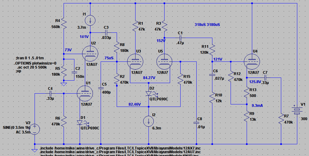
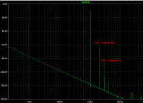
Going to 12AU7 second stage gives more reasonable gain but the distortion is not much better due no doubt to the higher overall HD2 in an AU7. So I thought to try a LTP for the second stage. I think it is the best yet. Reasonable gain and distortion numbers. Input is 5mV RMS (-49dB). Mid band voltage swing with that input is about 450mV peak. My concern was that the output voltage swing at 25Hz being 10 times higher at 4.5V peak might make for poor distortion performance at low frequencies but the simulations seem to indicate that HD2 would still be nearly 50dB down.
Of course I am simulating with ideal CCSs so real world won't be quite so good but the results seem promising enough to induce me to go to all the trouble of incorporating the sand and dinking around with heat-sinks. 🙂
Thoughts?
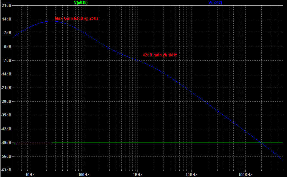
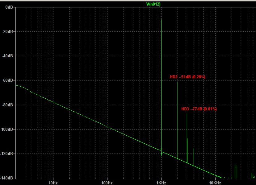
Attachments
- Status
- Not open for further replies.
- Home
- Amplifiers
- Tubes / Valves
- cascode distortion Spectrum.