Now that this discussion has gone the route of lower gain, I am surprised nobody has suggested a step-down transformer yet.
With the 6SN7's rp of about 8k to 10k ohms, an output transformer's primary L would have to be pretty large, no? Now it gets expensive, I fear. What's the budget?
--
The 6AH4 has a plate resistance of less than 2k, might not need a CF for that. Personally, I like running right off the anode and skipping a CF if at all possible.
Re: Step-down transformer
If you use a 6SN7 plate (rp = ca. 8k) as the load for the primary, and you want an F3 of 10Hz, the primary inductance of the transformer would need to be about 125H. Is such a thing available?
--
If you use a 6SN7 plate (rp = ca. 8k) as the load for the primary, and you want an F3 of 10Hz, the primary inductance of the transformer would need to be about 125H. Is such a thing available?
--
Wait... If you use the output from the cathode follower to the OPT, then the primary inductance would not need to be nearly as high.
Figure the output impedance of a 6SN7 CF is 500 ohms (roughly).
Now the primary L of the OPT only needs to be 20H to reach an F3 of 5Hz, correct?
You could use an Edcor transformer for that, I think. If you went with a parafeed config, the OPT wouldn't need to have an air gap.
--
Figure the output impedance of a 6SN7 CF is 500 ohms (roughly).
Now the primary L of the OPT only needs to be 20H to reach an F3 of 5Hz, correct?
You could use an Edcor transformer for that, I think. If you went with a parafeed config, the OPT wouldn't need to have an air gap.
--
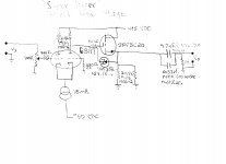
I ran a 6SN7 SRPP pre for years and really sorry I sold it. It was designed my John Hogan (passed away since). I drew out the schematic but it is on my other computer which will be here at the end of the month. I'll post it then.
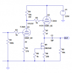
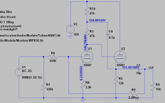
I was goofing around with this in LTspice, and came up with this. In simulation, it says THD at 2V RMS output is 0.08%, dominated by 2nd harmonic. Gain is about 10X.
--
--
Attachments
Last edited:
All great advice!
As far as gain goes I don't want more that 10, preferably less.
I have much to think about Now so thanks guys, my mind keeps thinking cathode repeater. I will pull out the data sheets later.....crunch some numbers and run some simulations.
The LTP setup I've uploaded has a gain less than 10. A "tall" B+ rail is required. Other folks have run simulations of the circuitry and found it to be extremely linear. It is possible to "play games" with absolute polarity.
Attachments
And we're back to the cathode-coupled amp! I like this because it still only uses one tube (MOSFET for the follower). Appy a bit of NFB to the second grid and you're golden. You dont' even need the CCS, so the B+ could be lower.The LTP setup I've uploaded has a gain less than 10. A "tall" B+ rail is required. Other folks have run simulations of the circuitry and found it to be extremely linear. It is possible to "play games" with absolute polarity.
We'r now post 31 and since post 8 no more mockingbird in sight.
I think we can stop barking up the tree, no more bird !
Mona
I think we can stop barking up the tree, no more bird !
Mona
He'll be back. And in greater numbers.We'r now post 31 and since post 8 no more mockingbird in sight.
I think we can stop barking up the tree, no more bird !
Mona

And we're back to the cathode-coupled amp! I like this because it still only uses one tube (MOSFET for the follower). Appy a bit of NFB to the second grid and you're golden. You dont' even need the CCS, so the B+ could be lower.
Hi Merlin and Eli. You mentioned that the cathode coupled amp doesn't need the CCS. Is that only if NFB is applied to the second grid? I'd think the linearity of the circuit would be dependent on balance between the two triodes, which could be enforced by a large impedance in the tail. If you ran it without a CCS in the tail and without NFB, wouldn't 2HD go up with any imbalance?
PS - Cathode coupled amp is definitely the best suggestion so far, with a follower on the output. Low input C, high input Z, low output Z, low THD, the desired gain. What's not to like?
It depends on both the AC and DC conditions. With a true LTP then yes, you generally want a very high tail impedance to cancel 2H, and that's as good as it gets, ignoring valve sample mismatch.You mentioned that the cathode coupled amp doesn't need the CCS. Is that only if NFB is applied to the second grid? I'd think the linearity of the circuit would be dependent on balance between the two triodes, which could be enforced by a large impedance in the tail. If you ran it without a CCS in the tail and without NFB, wouldn't 2HD go up with any imbalance?
But a cathode coupled amp is often not run with the same AC and DC conditions on each triode, so distortion cancellation is radically altered. You can get all sorts of distortion nulls depending on what parameters you play with. Adding a CF adds yet another layer of distortion cancellation on top, so it's rarely as simple as 'just bung a CCS in there and call it done'.
I would suggest a simple resistor tail for the OP as it minimises the gain in a simple way, and avoids impolite clipping and a -ve supply. In my book there is an example with a gain of x6 that manages 0.01% THD at 2Vrms using only a couple of 12AU7s and four resistors. That's just an example of what you can unexpectedly end up with by tuning the distortion cancellation. And that's with an average valve -who knows what the same topology could acheive with a 6SN7.
Last edited:
I'm talking about fig. 8.31. Yes I know it actually has six resistors but two of them are grid stoppers so they don't count 😉Interesting! I have your book at home, and I'll look that part up.

The guitar player in a friend of mines band quit and they have two gigs lined up this weekend and he asked to fill in. Although I do know maybe 10% of the material I am cramming to learn about 30+ songs so I haven't been as active in my own thread as I would like to be.
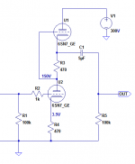
I have managed to read and ponder all schematics presented. The one I do like so far is the cathode coupled amp. I drew up a quick schematic and roughly simmed it. There are probably mistakes so please double check my work 🙂
.044% THD @ 2vrms out
Gain is roughly 6 which is about exactly where I want it to be.
I will sim all the suggestions and then move on to breadboard a few and see which I like the best.
I am excited!!!
Attachments
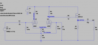
Here is Mike's augmented anode follower. It has .003%THD @ 2vrms into 100k, but driving heavier loads like 10k brings the distortion right up to .03%.
Gain is about 5x
The source follower is the clear winner for driving heavy loads. But this circuit is nice and maybe I should give it a listen when breadboarding.
Gain is about 5x
The source follower is the clear winner for driving heavy loads. But this circuit is nice and maybe I should give it a listen when breadboarding.
Attachments
- Status
- Not open for further replies.
- Home
- Amplifiers
- Tubes / Valves
- 6SN7 preamp advice