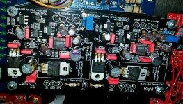
well these voltages are definitively wrong. it should be ~2,7 - 2,8V. before anything else this must be fixed. So first check: you did not install the 6.1 k resistor, right? only the current source? now did you trim all boards at 40mV? did you install the Rloads correctly and correct value? also check carefully if you have 8 Volt supply voltage at the DAC chips. Also post a nice high res image of the top dac board to check, also from the main board where the POS and NEG pins are
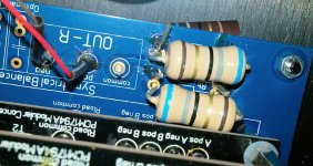
Hi Doede, the 6.1k resistor isn't on the board (although do I need to put a wire jumper in place instead?) Both channels of each deck are trimmed to 40mv. Rloads consist of 4 x 68r for each channel (I think this is correct for 4 decks)? Due to the size, I has to put 2 resistors on top and 2 underneath.
Just one question, how do I check the voltage at the DAC chips?
Thanks!
Attachments
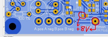
yes Rload is ok. For 8 Volt measuring see attached image.
To be brutally honest, your soldering is a mess. I see wires touching the ground plane on many places. You really need to tidy this up before anything else... also where wires are going through the boards
As the voltage is clearly too high, there is still something not ok, or broken. Can you also measure the resistance value from the combined Rloads, just to be sure? must be 34 Ohms. measure this on the top dac board between common and the 4 pins individually (Apos, Aneg, Bpos, Bneg), please post the the 8 values you get (left and right x 4) Of course not powered on
Attachments
Last edited:
yes Rload is ok. For 8 Volt measuring see attached image.
To be brutally honest, your soldering is a mess. I see wires touching the ground plane on many places. You really need to tidy this up before anything else... also where wires are going through the boards
As the voltage is clearly too high, there is still something not ok, or broken. Can you also measure the resistance value from the combined Rloads, just to be sure? must be 34 Ohms. measure this on the top dac board between common and the 4 pins individually (Apos, Aneg, Bpos, Bneg), please post the the 8 values you get (left and right x 4) Of course not powered on
Yes, the soldering on the output isn't my finest work. I also need to clean the flux so will tidy all of that up. I think I struggled with the size of the audio note resistors too. Feel a little embarrassed 😱
Resistance readings :
LEFT
A neg = 34
B pos = 34
A pos = 1k7
B neg = 1k7
RIGHT
A neg = 66
B pos = 66
A pos = 34
B neg =34
Doesn't seem right at all!
Hello,
Lots of people popping up with problems.
I did have a problem with one faulty board that was replaced. Never did hear the outcome from audiocreative what was wrong with it.
To me the best would be study the manual, take your time and first make it work like it is described in the manual before trying to improve it.
Greetings, eduard
Yes, the soldering on the output isn't my finest work. I also need to clean the flux so will tidy all of that up. I think I struggled with the size of the audio note resistors too. Feel a little embarrassed 😱
Resistance readings :
LEFT
A neg = 34
B pos = 34
A pos = 1k7
B neg = 1k7
RIGHT
A neg = 66
B pos = 66
A pos = 34
B neg =34
Doesn't seem right at all!
This looks like bad soldering joints at the wires going through the dac boards.
I would re-solder this(do all ! not only the A&B ones-just to be sure other stuff is not influenced as well) and measure again till all points are 34 Ohm
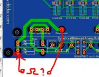
may be one check to see if all common tracks are still ok:
measure from the pins of the resistor at the outside of the board ( this is common) and the top located common as well GND at the input of the mainboard
please post these 4 values (left and right x 2 (top common & GND at input of board)
oh.... what about the 8 volt measurement?
Attachments
Yes, the soldering on the output isn't my finest work. I also need to clean the flux so will tidy all of that up. I think I struggled with the size of the audio note resistors too. Feel a little embarrassed 😱
Resistance readings :
LEFT
A neg = 34
B pos = 34
A pos = 1k7
B neg = 1k7
RIGHT
A neg = 66
B pos = 66
A pos = 34
B neg =34
Doesn't seem right at all!
I think you may have damaged the vias. This, together with the bad soldering (only on one side of the PCB) may have caused the issues...
Hello,
Lots of people popping up with problems.
I did have a problem with one faulty board that was replaced. Never did hear the outcome from audiocreative what was wrong with it.
To me the best would be study the manual, take your time and first make it work like it is described in the manual before trying to improve it.
Greetings, eduard
YES !!! please build a working DAC first without all kind of extra.
best to start with one Deck and than add more Decks... (think about changing Ra-b along adding Decks)
this make it much easier to detect errors
So far, I have seen two boards with defects on it. All other problems are mostly soldering and placing parts wrong.
Eduard, I believe your board had a wrong SMD transistor placed on it. Will not easily happen again, as AC build that in the shipping process now(to check all smd parts)
second one was a defective chip. Can happen...
pretty good score on the hundreds of boards being built
This looks like bad soldering joints at the wires going through the dac boards.
I would re-solder this(do all ! not only the A&B ones-just to be sure other stuff is not influenced as well) and measure again till all points are 34 Ohm
may be one check to see if all common tracks are still ok:
measure from the pins of the resistor at the outside of the board ( this is common) and the top located common as well GND at the input of the mainboard
please post these 4 values (left and right x 2 (top common & GND at input of board)
oh.... what about the 8 volt measurement?
OK, so I measure exactly 0.2ohm on each of the 4 measurements on the common tracks.
I will redo all the soldering and measure again.
Voltage on the chip on right is 8.31v and left is 8.30v
Last edited:
Some very good measurements to report!....
All 8 DAC chips measure between 8.27v and 8.35v
After significant tidying up of the soldering (mainly around the IV resistors) I am getting between 33.4ohm and 33.6ohm across the board at each terminal.
Finally I am getting 2.8v pretty much bang on for positive and negative to common on both channels.
I haven't had chance to fire it up and check it is now making music but from those measurements I'm now confident!
THANK YOU, especially Doede, for all the help. It is appreciated more than I can express 🙂
Will report back when I have tested it connected to an amplifier!
Just to Jeep the thread alive... Here's few pics of my humble single board DDDAC/Raspberry/Hifiberry/Moode Audio media player. I made the 5 V and 12 V power supplies according Doede's schematics to a perf board. Source is Raspberry pi 2 with Hifiberry DAC+pro which is working as a i2s reclocker and is connected to DDDAC via i2s. Not fancy on the outside, but the sound is great. Oh, and I just recently added a toslink to coax transformer board and new I can use toslink sources as well.
Edit: Hmm, I can add only one pic as an attachment. Maybe it's because of my iPad?
I finished building the dac yesterday, one board, caps on the output and a very basic power supply. Fired up and sounded ok from cold.
Can I ask how you use the hifiberry dac as a reclocker as I'm looking at the Kali to do that job but the hifiberry is cheaper?
Great kit Doede, next up are cinemags and a buffer board along with Salas SSLV shunts to power the dac and buffer. Still trying to decide the best way of powering the RPi/Kali.
Can I ask how you use the hifiberry dac as a reclocker as I'm looking at the Kali to do that job but the hifiberry is cheaper?
The Hifiberry DAC+pro board was connected via I2S wires from DAC+pro to DDDAC board's I2S input terminals. I used Moode Audio player in my RPI and I chose the DAC+pro driver from there, which should activate the DAC+pro clock circuits. The only problem was, that I had to upscale all the 16bit audio files to 24 bit by using Moode's upscaler. With 16 bit tracks there was only mono sound.
After I upgraded to Kali, I'm using generic RPI I2S driver in Moode and I have the stereo signal out without upscaling.
Some very good measurements to report!....
All 8 DAC chips measure between 8.27v and 8.35v
After significant tidying up of the soldering (mainly around the IV resistors) I am getting between 33.4ohm and 33.6ohm across the board at each terminal.
Finally I am getting 2.8v pretty much bang on for positive and negative to common on both channels.
I haven't had chance to fire it up and check it is now making music but from those measurements I'm now confident!
THANK YOU, especially Doede, for all the help. It is appreciated more than I can express 🙂
Will report back when I have tested it connected to an amplifier!
I GET MUSIC 🙂 🙂
First impression is that it's really detailed and dynamic. The drums at the start of 6 o'clock by Dream Theater just fly out of the speakers!!!
I had problems using it with Dirac Live as it didn't seem to like the indirect routing of Jriver to Dirac to waveio (music was slow and crackling). Luckily there is a Vst version which I loaded into jriver and can now route direct to the waveio.
The only thing I notice is a noticeable hiss from both tweeters when no music is playing and a very faint buzz (only heard with ear next to speaker) from the bass driver. My amp has always been dead silent. Anyone else get this? It's my first time going 100% balanced so may have done something slightly wrong.
I have a load resistor between pin 2&3 on the dddac xlr sockets along with the orange and yellow outputs from the cinemas. I don't have pin 1 connected to anything (should this be grounded to chassis)? On the amp side, pin 1 on the xlr sockets are grounded to chassis.
Last edited:
I GET MUSIC 🙂 🙂
First impression is that it's really detailed and dynamic. The drums at the start of 6 o'clock by Dream Theater just fly out of the speakers!!!
I had problems using it with Dirac Live as it didn't seem to like the indirect routing of Jriver to Dirac to waveio (music was slow and crackling). Luckily there is a Vst version which I loaded into jriver and can now route direct to the waveio.
The only thing I notice is a noticeable hiss from both tweeters when no music is playing and a very faint buzz (only heard with ear next to speaker) from the bass driver. My amp has always been dead silent. Anyone else get this? It's my first time going 100% balanced so may have done something slightly wrong.
I have a load resistor between pin 2&3 on the dddac xlr sockets along with the orange and yellow outputs from the cinemas. I don't have pin 1 connected to anything (should this be grounded to chassis)? On the amp side, pin 1 on the xlr sockets are grounded to chassis.
Well done mate
Hello,
It seems Billy boy did call it a Day?
billyboyk, don't give up! And if you do, I'd be happy to recycle your DDDAC... ;-)
Hello everybody !
I'm alive 😀 but since 2 weeks, there are a lot of family/friends at home and I don't have time for my DDDAC.
Still problems with my system BUT, it works perfectly if I replace my tube amps with solid state amp. I will be back in few days for fix it with your great help.
Have a nice end of year ! 😛
Do you have schematics of your amp input sections? Can you draw it up at least for the tube amp?Hello everybody !
I'm alive 😀 but since 2 weeks, there are a lot of family/friends at home and I don't have time for my DDDAC.
Still problems with my system BUT, it works perfectly if I replace my tube amps with solid state amp. I will be back in few days for fix it with your great help.
Have a nice end of year ! 😛
Happy new year everybody ! 😛
Everybody has left our house, so now I have time 😉
Yes, it is like this:
The amp part is pretty the same than this:
http://www.keith-snook.info/amplifier-hifi-schematics/Williamson amplifier 1949.pdf
Except that I use UL mode and auto bias for EL34 in class A.
Everybody has left our house, so now I have time 😉
Do you have schematics of your amp input sections? Can you draw it up at least for the tube amp?
Yes, it is like this:
An externally hosted image should be here but it was not working when we last tested it.
The amp part is pretty the same than this:
http://www.keith-snook.info/amplifier-hifi-schematics/Williamson amplifier 1949.pdf
Except that I use UL mode and auto bias for EL34 in class A.
An externally hosted image should be here but it was not working when we last tested it.
Ok, so you've connected the NEG output to GND. I'd guess the DAC chips are upset by this. You'd be better off to connect the DDDAC output as described in the manual (or on dddac.com).
- Home
- Source & Line
- Digital Line Level
- A NOS 192/24 DAC with the PCM1794 (and WaveIO USB input)