I'm looking to build a valve preamp to go in front of a DCPP:
* source selection (DAC, valve phono, line level RCAs)
* volume control (stepped attenuator)
- balance
- tone control (Baxandall)
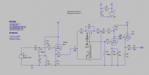
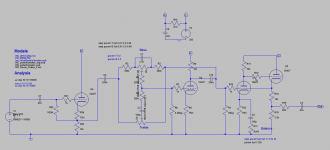
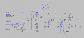
The 1st two are handled by an available passive module. The output of the module would then flow in to the active section. I concocted this from Merlin's new book and Max Robinson / RCA manual.
The input stage is a fixed bias cathode follower using 1/2 a 12AU7.
The tone stack is an active Baxandall with feedback from the 2nd 12AT7 stage. I included R1 = 22k to keep the output close to 0dB when the controls are at mid points. The output comes from a 12AT7 CF.
Other than wanting to know if this looks a sensible approach, I have the following questions:
1) Is it possible to get, say, 3-6dB gain through the circuit to allow for quieter sources / losses due to attenuator or balance control?
2) Where would a balance control go? (ideally one using a single gang pot in an active fashion)
For (1) I thought of bootstrapping the 2nd stage, but I think that messes the feedback.
For (2) I had hoped I could use the bottom of C16 through a pot to the grounded wiper (with the other channel coming in the other side), but that doesn't seem to work (only giving 0.5dB reduction).
Many thanks,
Tristan
* source selection (DAC, valve phono, line level RCAs)
* volume control (stepped attenuator)
- balance
- tone control (Baxandall)
The 1st two are handled by an available passive module. The output of the module would then flow in to the active section. I concocted this from Merlin's new book and Max Robinson / RCA manual.
The input stage is a fixed bias cathode follower using 1/2 a 12AU7.
The tone stack is an active Baxandall with feedback from the 2nd 12AT7 stage. I included R1 = 22k to keep the output close to 0dB when the controls are at mid points. The output comes from a 12AT7 CF.
Other than wanting to know if this looks a sensible approach, I have the following questions:
1) Is it possible to get, say, 3-6dB gain through the circuit to allow for quieter sources / losses due to attenuator or balance control?
2) Where would a balance control go? (ideally one using a single gang pot in an active fashion)
For (1) I thought of bootstrapping the 2nd stage, but I think that messes the feedback.
For (2) I had hoped I could use the bottom of C16 through a pot to the grounded wiper (with the other channel coming in the other side), but that doesn't seem to work (only giving 0.5dB reduction).
Many thanks,
Tristan
Attachments
Last edited:
Is it possible to get, say, 3-6dB gain...
Where would a balance control go?
I have used an "anode follower" as 1st stage to get some gain and to have the balance pot at the NFB loop.
R13 (50k) represents as half of the 100k balance potentiometer.
Attachments

You should get some performance improvement by moving the feedback connection (right end of R1) to U11 cathode. I don't see any simple way to add a single-element balance pot.
I have used an "anode follower" as 1st stage to get some gain and to have the balance pot at the NFB loop.
R13 (50k) represents as half of the 100k balance potentiometer.
Ah, so that could be an option. Ditch the 1st CF, run it as a normal gain stage with the AF reducing the gain somewhat.
You should get some performance improvement by moving the feedback connection (right end of R1) to U11 cathode. I don't see any simple way to add a single-element balance pot.
Thanks Mike. Is that less phase shift? Simming it just now looks close to before, but not sure how to judge the performance.
Updated Schematic
Thanks for the pointers.
I've made a couple of changes:
- 1st stage is now a standard 12AX7 gain stage, but with a split plate load to provide attenuation.
- Feedback to the stack taken from the cathode of the CF
The advantage of having a standard 1st stage is that I can now have an active balance control at the base of C9 - a 5k lin pot. At its center setting I get just under 3dB gain across the circuit, ranging from ~2.2dB to 6.75dB.
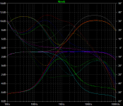
Varying the bass control gives +/- 9dB, treble about the same.
The value of R13 is quite key to get a flat response - 4.7k to 5.5k seems about right.
How does this look?
Thanks for the pointers.
I've made a couple of changes:
- 1st stage is now a standard 12AX7 gain stage, but with a split plate load to provide attenuation.
- Feedback to the stack taken from the cathode of the CF
The advantage of having a standard 1st stage is that I can now have an active balance control at the base of C9 - a 5k lin pot. At its center setting I get just under 3dB gain across the circuit, ranging from ~2.2dB to 6.75dB.
Varying the bass control gives +/- 9dB, treble about the same.
The value of R13 is quite key to get a flat response - 4.7k to 5.5k seems about right.
How does this look?
Attachments
- 1st stage is now a standard 12AX7 gain stage, but with a split plate load to provide attenuation.
I could also use at 12AU7 in this position to reduce the attenuation needed. I'd tweak R13 to 10k to balance the response at center settings.
Attachments
How about like this 🙂
Mona
Thanks Mona - I've opened a can of worms on this. Been reviewing as many schematics / text books on this as I can. As far as I can see it may be better to have:
Bax stack -> Gain stage (fedback to Bax) -> Gain stage (balance control on bypass cap) -> Cathode Follower (with split cathode resistor to control overall gain)
I'll play around in SPICE and see what looks best, but then I'm wary of venturing too far from a known / trusted schematic...
Latest iteration
This is my latest iteration. Extensive re-reading of Merlin's book and Max Robinson's website, plus some googling of existing schematics.
Would appreciate someone having a glance over it.
An overview:
- ~3dB gain across the circuit with neutral controls
- Balance control
Detailed:
- Cathode biased CF 12AU7 input stage to buffer from the preceding stepped attenuator / sources
- Baxandall active stack with 12AU7 gain stage, unbypassed although this could be LED biased.
- 12AU7 gain stage with Balance control on bypass capacitor providing ~3dB variation between channels
- 12AU7 CF with split bias resistor to attenuate the output signal and give low impedence to drive the power amp
The response seems very flat at neutral, with plenty of gain / cut with control changes.
I've tried to follow the advice in Merlin's book to ensure reduced slew distortion, and kept the operating points where I think distortion is minimised. But I'm sure there are improvements that could be made.
A reminder - my goal is to allow low output devices to drive the DCPP, as well as CD players / DACs etc. So I'd like a bit of 'headroom' to the volume control that feeds the preamp.
Attachments
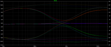
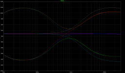
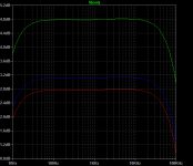
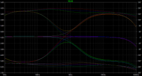
Further slight modifications: changing the operating point of the 3rd stage to ~3.3V, slightly hotter than before. Voltages are marked on the schematic, and freq, phase and the effect of the balance pot are attached.
A 1.4Vpp signal in gives 2Vpp at the output.
The circuit's low impedance output (~418ohm) should be sufficient to drive the DCPP's 100k input.
The circuit's high impedance input (which could be made better by using fixed bias) should be fine for most sources.
Does this look a sensible approach?
It would be great to reduce the valve count from 4 to 3 if anyone knows a clever way to achieve this?
Attachments
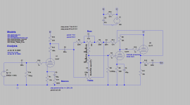
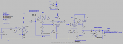
Some further alterations based on some eBay valve purchases - some 12AT7s and 12AU7s.
- 1st two stages to 12AT7 with LED bias for ~2V
- lower input cap to 4.7n
- tweak to operating points for stage 3 and 4
- added output protection
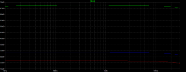
This gives ~3dB gain and <0.2dB variation from 10Hz to 25kHz with the controls at centre settings. And <0.06dB variation from 10Hz to 40kHz with the tone stack bypassed.
The balance control gives ~1.5dB variation, so ~3dB with two channels.
I'd adjust the ratio of R15 : R16 to set the 3dB level on test.
As for distortion levels, this is where I'm clueless. I've tried to keep the operating points on the more linear parts of the transfer curves (so higher V_a and lower bias point) whilst being aware of grid current limits if the bias is too low.
Is this a good approach?
I'm worried that if I can't find a similar schematic on google then I must be doing some very wrong...
Spice netlist attached. Models in the zip file.
- 1st two stages to 12AT7 with LED bias for ~2V
- lower input cap to 4.7n
- tweak to operating points for stage 3 and 4
- added output protection
This gives ~3dB gain and <0.2dB variation from 10Hz to 25kHz with the controls at centre settings. And <0.06dB variation from 10Hz to 40kHz with the tone stack bypassed.
The balance control gives ~1.5dB variation, so ~3dB with two channels.
I'd adjust the ratio of R15 : R16 to set the 3dB level on test.
As for distortion levels, this is where I'm clueless. I've tried to keep the operating points on the more linear parts of the transfer curves (so higher V_a and lower bias point) whilst being aware of grid current limits if the bias is too low.
Is this a good approach?
I'm worried that if I can't find a similar schematic on google then I must be doing some very wrong...
Spice netlist attached. Models in the zip file.
Attachments
Last edited:
Hi Tristan,
The 12AT7 is not very linear so your best hope is usually to use a loarge load impedance and bias it as hot as possible if you want the lowest distortion (which will still not be very low). However, since your application uses local feedback the distortion will of course be much lower -less than 0.02% at 1Vrms (e.g. fig. 9.24 of my book). Distortion in the CFs will be lower still and can usually be ignored. Overall, therefore, distortion in this circuit will be dominated by the 12AU7 gain stage and will be about 0.1% at 1Vrms (e.g. fig. 6.25), though this too will fall as the balance pot is brough into play.
Just noticed R15/R16. Why are you attenuating the output level so much? You already have protection clamping diodes so the output voltage can't get dangerously high if you take it directly from the cathode. And if you don't need the gain, don't use the gain stage!
Last edited:
Just noticed R15/R16. Why are you attenuating the output level so much? And if you don't need the gain, don't use the gain stage!
Thanks Merlin.
R15/R16 is to get the 3-6dB gain across the circuit - idea being to allow 'weaker' sources (the Wolfson DAC from my RaspberryPi, e.g.) to drive the DCPP to full (2V input apparently). The gain stage also facilitates the balance control.
Input CF/buffer -> Bax stage -> Gain stage + balance -> output CF/buffer
Am I being stupid in wanting to add such a little amount of gain vs the extra valve + distortion etc etc?
If I am, then removing the gain stage and shifting the balance control along wit a few tweaks here and there (input CF -> Bax + balance -> output CF) gives ~-1dB gain. Taking the feedback from the output cathode improves the phase plot too. (basically copying http://www.angelfire.com/electronic/funwithtubes/images/Amp-Tone-7-A-A.gif but using 12AU7s or 12AT7s). But the balance control becomes rubbish.
Alternatively, switching the input to a normal gain stage (input gain + balance -> Bax -> output CF) gives ~20dB gain, which I can attenuate down to 3-6dB with a split plate load. Again feedback from the output cathode. But this has the distortion issue of the gain stage.
Both these versions get my valve count down though!
If you need a tiny amount of gain I think I would make the gain stage into a virtual earth amp, with feedback taken from the output. Then use a passive balance pot at the input of the whole circuit, or maybe continue to do it in the VE amp (because with such a small feedback factor it may still be possible to get enough gain variation through the cathode degeneration pot).
Thanks Merlin, but I think this is is getting a bit above my head. I could just get a better DAC for the Pi, and assume all other sources are at, or close enough to, line level! Although the main issue is with the TV's digital out - each HDMI source seems to have a vastly differing level, with no way to compensate...
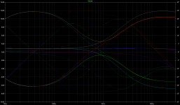
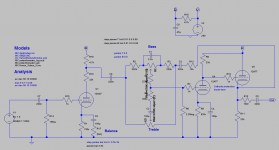
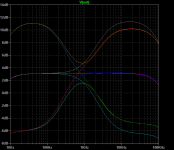
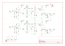
Attached is a simplified schematic - 3 stages: input CF -> Bax with gain stage -> output CF. Basically that Fun with Tube's schematic but with altered values. What do you reckon?
I guess I'm OK using either the 12AU7s or 12AT7s, or a mix of the two throughout? Distortion shouldn't be a problem, and my main target is keeping the overall gain as close to unity as possible.
Although the LTSPICE sims look good using 12AT7s... (attached Freq response).
T
Attachments

Yes that looks better. You don't particularly need R22; I would move it to the very output instead. Also don't forget to include a protection diode between grid and cathode of V5.
You could increase R2 to 330k which would give you about 3dB gain at the flat setting. Only downside is that the flat setting will no longer be with the pots dead centre, so the sensitivity of the pot rotations will no longer be symmetrical, but does that matter to you?
Also I would recommend a fixed-biased CF at the input, rather than a self-biased one, for reasons explained in my book.
Last edited:
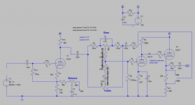
Cheers - yes, added and modified as suggested. Interesting about increasing R2 - not sure it would be worth the bother though:
Looking at the DCPP input loadline (my attempt, could be wrong: HT = 335V, Ra = 30k, Ia = 6.8mA) suggests bias is ~-2.75V. But given the shallow gradient am I right in thinking the grid only really swings up to -2V before bunching?
So we'd want a preamp to supply 1.5Vpp / ~1Vrms. But this is not counting the 10% Schade feedback to the input plates. And ~80Vpp (160Vpp/2 as it's a diff amp stage) output swing is enough for the output stage by my reckoning.

So a close-to line level source (2Vrms?) losing 1dB across the preamp is fine?
Attached is the latest schematic, and the start of my next challenge!
Looking at the DCPP input loadline (my attempt, could be wrong: HT = 335V, Ra = 30k, Ia = 6.8mA) suggests bias is ~-2.75V. But given the shallow gradient am I right in thinking the grid only really swings up to -2V before bunching?
So we'd want a preamp to supply 1.5Vpp / ~1Vrms. But this is not counting the 10% Schade feedback to the input plates. And ~80Vpp (160Vpp/2 as it's a diff amp stage) output swing is enough for the output stage by my reckoning.
So a close-to line level source (2Vrms?) losing 1dB across the preamp is fine?
Attached is the latest schematic, and the start of my next challenge!
Attachments

I'm not familiar with the DCPP, but your above comment is correct.am I right in thinking the grid only really swings up to -2V before bunching?
Also, take your Lfb/Rfb from the other side of the 100R build-out resistors.
- Home
- Amplifiers
- Tubes / Valves
- Active Bax Preamp - review request