I can't understand why in a circuit with some amount of amolification is used a resistive partitor in output to have -6dB of gain.
Is much better to use a tube with lower gain and lower Rp so the job is easier.
And I put this link, look post 15
Tube tone control baxandall
It is working tested on lab non virtual simulation
Walter
Is much better to use a tube with lower gain and lower Rp so the job is easier.
And I put this link, look post 15
Tube tone control baxandall
It is working tested on lab non virtual simulation
Walter
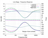
This circuit has greater than -1dB gain - see attached LTSPICE measurements and actual readings. There's no resistive divider on the output.
Attachments
Last edited:
On your diagram there is a big error around 1kHz that is a center frequency.
In the mid position of both pots the levels (at 1 kHz) must be same as the position is full clockwise or full counterclockwise!
In your case there are almost 2 dB of difference
But, of course, this is simulation!
Walter
In the mid position of both pots the levels (at 1 kHz) must be same as the position is full clockwise or full counterclockwise!
In your case there are almost 2 dB of difference
But, of course, this is simulation!
Walter
These are real readings from an actual running system plotted over simulation (yellow dotted). The match is pretty good I thought (allowing for component tolerance etc), and very much in line with those in Merlin's book.On your diagram there is a big error around 1kHz that is a center frequency.
In the mid position of both pots the levels (at 1 kHz) must be same as the position is full clockwise or full counterclockwise!
In your case there are almost 2 dB of difference
But, of course, this is simulation!
Yes, I can see ~2dB difference, but for my needs (minor adjustments) is good enough. I also see slight variation in the simulations here: Practical Tone Controls.
To be honest, I've left my controls at their mid-point for the last year approx, so the preamp is running as simply a buffer...
For anyone interested in the future - I've put all the source files (KiCAD) and gerbers for this PCB build (with the minor error corrected) here: amps/HiFi-Baxandall-Pre at master * tristancollins/amps * GitHub