Both, one channel with cap + alps pot, other channel with cap + autotransformer, same result 🙁
Ok, that smells like your problem is not (only) related to the autoformer. But, to be entirely sure, I'd try again with the autoformer disconnected.
What are the DC voltages across the load resistors (with one deck, two decks)?
Hi mate, I thought I knew what you meant by wiring in series but it appears I don't. 🙁It seems that you plugged it in parallel, if you want to add the voltage, you must plug it in serial 😉
Are you referring to the way the transformer secondaries are wired into the PSU board?
If this is the case how would I wire them in series?
Thanks
Hi mate, I thought I knew what you meant by wiring in series but it appears I don't. 🙁
Are you referring to the way the transformer secondaries are wired into the PSU board?
If this is the case how would I wire them in series?
Thanks
handle each power supply as they are. Transformer winding in, Plus/Minus 3,3 Volt out. Now connect one Minus output to the Plus output of the other power supply (don't bother which one) and now you will end up with a left open Plus wire from one board and a Minus wire from the other board. these are your new plus/minus 6,6 Volts
Hello !
I have removed the autoformer, replaced it by ALPS 10K.
First Dac board in place, it sounds perfect, DC voltage on load resistors: 2.7V
Second Dac board, distortion is back BUT, only on very low volume. Same voltage on load résistors.
I noticed that I can still hear sound even the pot on min position, by this time, the little sound is VERY saturated.
I noticed also that when I mesure DC voltage on load résistors, the distortion increase a lot.
It seems that I have a load problem...
Ok, that smells like your problem is not (only) related to the autoformer. But, to be entirely sure, I'd try again with the autoformer disconnected.
What are the DC voltages across the load resistors (with one deck, two decks)?
I have removed the autoformer, replaced it by ALPS 10K.
First Dac board in place, it sounds perfect, DC voltage on load resistors: 2.7V
Second Dac board, distortion is back BUT, only on very low volume. Same voltage on load résistors.
I noticed that I can still hear sound even the pot on min position, by this time, the little sound is VERY saturated.
I noticed also that when I mesure DC voltage on load résistors, the distortion increase a lot.
It seems that I have a load problem...
Hello Billy,
Or you sure the resistors are in the exact right Spot? Maybe one of them is out of specs or there is a bad connection between the resistor body and the end Cap?
You surely have a strange dac.
Greetings, Eduard
Or you sure the resistors are in the exact right Spot? Maybe one of them is out of specs or there is a bad connection between the resistor body and the end Cap?
You surely have a strange dac.
Greetings, Eduard
handle each power supply as they are. Transformer winding in, Plus/Minus 3,3 Volt out. Now connect one Minus output to the Plus output of the other power supply (don't bother which one) and now you will end up with a left open Plus wire from one board and a Minus wire from the other board. these are your new plus/minus 6,6 Volts
Perfect thank you, I have one more question for anybody who can answer .
I have completed the half clock upgrade on the red board is there any way of testing that the red board is working as it should before I Wire a dac board
Onto it?
Thanks
Hello,
I am glad I finished my dad and the last time I used it with the aurender it was working !
Because mine is truly heavy I will probably not be triggered to make any changes when I am back home.
It seems lots of modifications end up with people getting into problems which are hard to get rid of.
The only mods I did do were all related to the power supply like the use of choke input, other caps, bells on regulators instead of the lf type. The 10 volt preregulator is still the original one. Replacing it with bells on would be to much work.
Did might be my hobby but not this kind of thing. To much desoldering for Me!!
What I wanna try is using the lundahl ll1662 isolation transformer for the aurender and the dac It could be an Improvement? Maybe both devices their own ll1662
Greetings, eduard
I have removed the autoformer, replaced it by ALPS 10K.
First Dac board in place, it sounds perfect, DC voltage on load resistors: 2.7V
That looks good to me.
Second Dac board, distortion is back BUT, only on very low volume. Same voltage on load résistors.
I assume you also changed the load resistors? The load resistors (POS-GND and NEG-GND) should be 133Ω for a single DAC board and 68Ω for two boards. If you didn't change the resistors, I would be suspicious about the fact that you get the same DC bias voltage with two boards although you should have twice the bias current.
I noticed that I can still hear sound even the pot on min position, by this time, the little sound is VERY saturated.
Is this the same for single/dual boards? Does the volume pot go all the way to zero ohms?
I noticed also that when I mesure DC voltage on load résistors, the distortion increase a lot.
Poor solder joint at the load resistors? Broken resistor?
Easy test: Try using the NEG output instead of the POS and see if this behaves the same.
Can you post a photo of your setup?
Perfect thank you, I have one more question for anybody who can answer .
I have completed the half clock upgrade on the red board is there any way of testing that the red board is working as it should before I Wire a dac board
Onto it?
Thanks
Only with good scope or logic analyzer I am afraid...
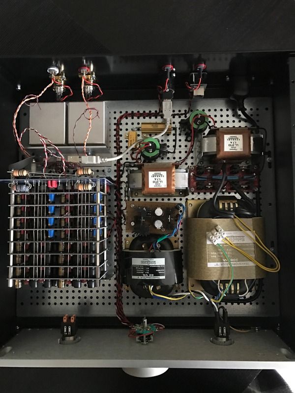
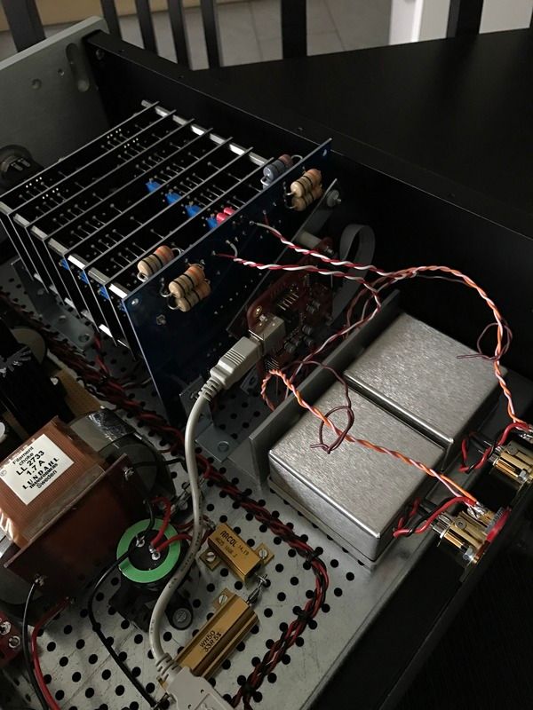
After months of work my latest version of this amazing DAC is mostly done, DIY projects are never really fully completed
Few pics below for you and just a stunning sounding DAC. You will see I can't get the lid on now as the design grew beyond my original plan but no big issue for me
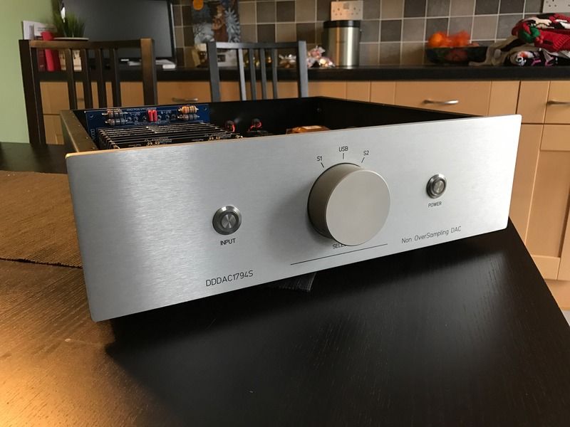
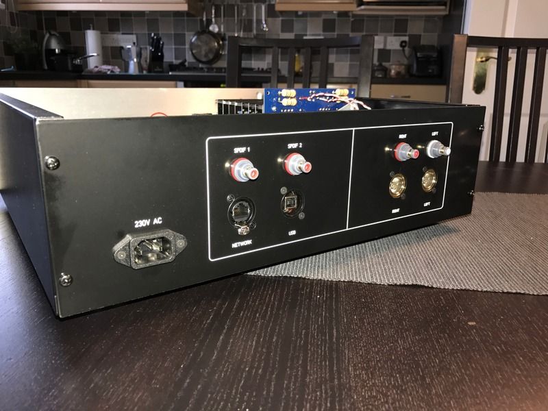
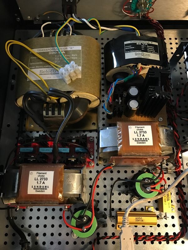
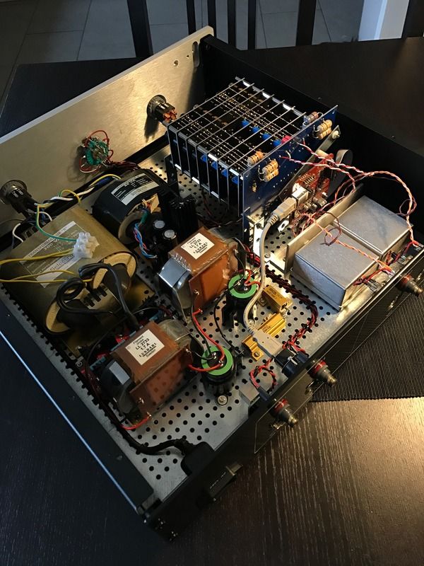
Few pics below for you and just a stunning sounding DAC. You will see I can't get the lid on now as the design grew beyond my original plan but no big issue for me


Congratulations Simon, you show that with endurance, time and patience you arrive at your declared goals! Also I see great workmanship 
One question, what was de original thought behind the, not connected, switch Named input ?
One question, what was de original thought behind the, not connected, switch Named input ?
Congratulations Simon, you show that with endurance, time and patience you arrive at your declared goals! Also I see great workmanship
One question, what was de original thought behind the, not connected, switch Named input ?
Thank you Doede and special thanks for all your help and time!
The thinking of the input switch is a simple one. I wanted the balance and look of the front panel to look right no more! Ha ha
Also I wanted to future proof for any design changes and why network connector on the back is there but not used today
Lovely work Simon. That front panel is fantastic.
Cheers mate
Hello all,
I intent to build a DDAC with tubes output in SRPP configuration using 6N2P and lampizator schematic, but when I connect the output of the DAC to the input of the tube I am not getting any amplification an the SQ is very bad. I am pretty sure that the tube wiring is done well, so maybe is something related to the DAC? What measurements can I make on the DAC?
More details about this problem is on this topic: http://www.diyaudio.com/forums/digital-line-level/300885-pcm-1794-tube-output-problem.html
Thank you !
Hello all,
I intent to build a DDAC with tubes output in SRPP configuration using 6N2P and lampizator schematic, but when I connect the output of the DAC to the input of the tube I am not getting any amplification an the SQ is very bad. I am pretty sure that the tube wiring is done well, so maybe is something related to the DAC? What measurements can I make on the DAC?
More details about this problem is on this topic: http://www.diyaudio.com/forums/digital-line-level/300885-pcm-1794-tube-output-problem.html
Thank you !
I answered you on your thread....
What was the best tube output schematic used by members with DDAC?
Sorry for this question but this topic has 588 pages 🙂
Sorry for this question but this topic has 588 pages 🙂
What was the best tube output schematic used by members with DDAC?
Sorry for this question but this topic has 588 pages 🙂
The DDDAC does not need a tube output per se... The output is 1,25 Volt Eff 0dB, so enough for any amplifier. The output impedance is lower than most normal Tube stage. So again no need for this.
If you want a tube amplifier as Pre amplifier, fine, that is what I use as well. I just want to make clear that the are many DACs with "a tube output" as it sounds "high end" 😱 but this DAC will not get "better" by using a tube output of any kind.
So if you already have a good pre-amplifier you're good to go with the DAC as is....
my 2 cents worth 😀
Hi Doede,
Maybe you don't received my emails... the Sowter transformers are still available?
Thanks and Regards,
Enrico
Maybe you don't received my emails... the Sowter transformers are still available?
Thanks and Regards,
Enrico
Are they getting scarce?Hi Doede,
Maybe you don't received my emails... the Sowter transformers are still available?
Thanks and Regards,
Enrico
- Home
- Source & Line
- Digital Line Level
- A NOS 192/24 DAC with the PCM1794 (and WaveIO USB input)