Hi,
I'm working on a dual mono amplifier, and each channel will have one 430VA transformer and 4x 10,000uF filter caps.
I would like to protect my household electrics and also the expensive capacitors so I planned to implement a current-limiting soft-start switch from Rod Elliot (ESP).
Now, each of my transformers is not exactly a monster but I'm more worried about the current appetite of the filter caps. By limiting the (240V) mains supply to 9.6A (4.8A to each transformer) I can pretty much guarantee the transformers an easy ride, each receiving just 267% of rated power for the first 100 ms. Should be stone cold anyway.
My question is really - what next? After 100 ms, the filter caps will be no more than 25% to 50% charged I guess, receiving 21A from 55V rails. When the relay chops out the resistors, I'm worried about the caps drawing HUNDREDS of amps as they charge up to 100%.
2 specific questions if I may:
Which is these configurations is the least-worst? Is high inrush current 'normal? What are sensible limits? I know of amps running 625VA/40mF without any kind of current limiting so I'm confused. Please shine the light of wisdom on me.
I'm working on a dual mono amplifier, and each channel will have one 430VA transformer and 4x 10,000uF filter caps.
I would like to protect my household electrics and also the expensive capacitors so I planned to implement a current-limiting soft-start switch from Rod Elliot (ESP).
Now, each of my transformers is not exactly a monster but I'm more worried about the current appetite of the filter caps. By limiting the (240V) mains supply to 9.6A (4.8A to each transformer) I can pretty much guarantee the transformers an easy ride, each receiving just 267% of rated power for the first 100 ms. Should be stone cold anyway.
My question is really - what next? After 100 ms, the filter caps will be no more than 25% to 50% charged I guess, receiving 21A from 55V rails. When the relay chops out the resistors, I'm worried about the caps drawing HUNDREDS of amps as they charge up to 100%.
2 specific questions if I may:
- Is it a really bad idea to let the current at the caps spike to 100 amps for 15 milliseconds or so? After that it will dip again below the max continuous figure of 28A.
- What is the best current limit to use to ensure that the transformer is not aged prematurely and also to prevent melted wire or popped caps. (maybe I'm worrying too much?)
Which is these configurations is the least-worst? Is high inrush current 'normal? What are sensible limits? I know of amps running 625VA/40mF without any kind of current limiting so I'm confused. Please shine the light of wisdom on me.
Start with PSUD2. It will push you to take some important basic resistance measurements, and give you a good appreciation of what currents actually flow at start up. Hopefully you can post a screen grab for us.
one more thing to add - the filter caps are arranged 2 in parallel on each rail, so actually the 30,40,50A being consumed is being distributed to 4 capacitors so I guess they are actually within spec?
Even +/-55V 100A supplied to each mono channel can be swallowed by 4 caps @ 25A each? Is my logic sound?
What about wiring? Wikipedia says 20 AWG (0.8mm) wire can withstand 150A for 1.0 second. No problem then?
Even +/-55V 100A supplied to each mono channel can be swallowed by 4 caps @ 25A each? Is my logic sound?
What about wiring? Wikipedia says 20 AWG (0.8mm) wire can withstand 150A for 1.0 second. No problem then?
Most people seem to get away with one resistor and relay.
Personally I use a simple triac based design using an 8 pin PIC micro.
It just ramps up the phase angle slowly until it reaches 100% and stays there until mains is removed.
Once mains reappears the loop starts again.
Personally I use a simple triac based design using an 8 pin PIC micro.
It just ramps up the phase angle slowly until it reaches 100% and stays there until mains is removed.
Once mains reappears the loop starts again.
The interesting thing about electrolytics are that guidelines and datasheets rarely (if ever) identify peak current capability - or damage information. The closest test I think is IEC 60384-4 clause 4.2, which subjects a capacitor to a million charge/discharge cycles where the charge and discharge times are 0.5 second each, and the charging/discharging circuit applies an RC time constant of 0.1s, with the charge voltage being the capacitor rated voltage.
I'm thinking the peak charge/discharge current for that test is way less than a typical ss amp power supply environment.
There are general comments that electrolytics are pretty bullet proof for turn-on surge current capability, as in a power supply.:
Switching Power Supplies A to Z, By Sanjaya Maniktala, page 262.
The various circuit resistances, mainly from the effective transformer winding resistances but including the diodes and capacitors internal resistance, will effectively limit the peak current during turn-on charging to so that some number of mains cycles of current pulses are needed to charge the cap up.
Of more importance is checking the diodes peak current capability and comparing that back to a PSUD2 estimate.
So in essence, there is no benefit to capacitor lifetime by using a slow start circuit - although there may be other benefits, of which fuse selection is probably the more important one to consider.
Yep choice of fuse is weighing on my mind - I don't want to end up using a high rating specifically to accommodate startup.
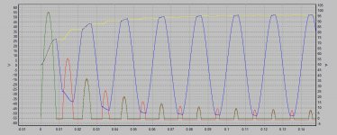
See sim results attached. I think the architecture is correct for the + rail running off a centre-tap transformer. I couldn't figure out how to add another capacitor so I just doubled the capacitance and halved the ESR.
Without soft-start, peak current for first cycle is 100A, but second cycle peak is 55A. Not as bad as I feared. Great tool.
Attachments
consider also the transformer impedances, taken together with the caps...
do not look at filter caps alone...
Patrick Turner put it very well....powersupplies
do not look at filter caps alone...
Patrick Turner put it very well....powersupplies
I agree AJT, those resistances look very low - you'd need some care to make measurements that ended up giving the part values in the sim.
> 50% charged I guess, receiving 21A from 55V rails.
Do not "guess". Would you build a bridge, even a dog-porch, on a guess?
You can use rough numbers, and fold-over duplicates, if you remember your short-cuts and allow for them.
Let's try hot-start. After all thousands of large amps have been powered-up at home without any fancy start-rig.
Simplify to 40VAC. 400VA transformer, 40V 10A. 4 Ohms. A 400VA may have 5% regulation. So there's about 0.2 Ohms of transformer impedance (mostly resistance). Check: 10A in 0.2 Ohms is 2V. 2V is indeed 5% of 40V.
At turn-on the current tends to go to 40V/0.2r or 200 Amps.
The voltage ratio is 240:40 or 6:1. The primary current is 200A/6 or 33A. Assuming a 16A subcircuit, a short-term 2X overload is not a problem. Many large motors draw a 4X overload. My well-pump has pulled 44A to start (11A to run), on a 20A circuit, a dozen times a day, for 30 years.
Now we are charging (??) 88,000uFd through 0.2 Ohms. Time-constant is 0.018 seconds. The time to heat wall-wires, or blow-out fuse, at 2X overload, is minutes, not seconds, not milliSeconds. Hot-start is not a risk for your house wiring.
Lamp-dim: when my well-pump starts the lights dim. But this is due to a too-long wire from the street. In a proper system we expect at-most 2% sag when one circuit is loaded to 100%. So 4% sag for 33A on a 16A circuit. Incandescents will dim momentarily. Altho a 0.017s time-constant is shorter than a filament's thermal time, so maybe imperceptible.
The Most Likely failure, for most designers, is rectifier current rating. We both agree first-cycle is 100A per rectifier (200A in my folded-over simplification). But by the time you can read a meter it is under 5A. Rectifiers have a long-term rating and a one-cycle rating. Older types plotted how many cycles at how much current. This was often ignored. Result was a box that turned on 100 or 1,000 times, and then quit "for no reason". Cure was always to go at least 3X up from the original current rating. If in doubt, go 3X from the secondary nominal current. In this case, 25A or 50A rectifier! Back in 1976 this would have been costly. In this 21st century rectifiers are fairly cheap. DigiKey shows 18 50A rects under $5. And a big rect looks good.
60ohms of added resistance in the primary of each transformer will do as a soft start for 430VA 230Vac transformers. That will allow a T2A mains fuse for each transformer. You will probably find that the pair will start reliably with a T3.1A fuse at the IEC incomer.Hi,
I'm working on a dual mono amplifier, and each channel will have one 430VA transformer and 4x 10,000uF filter caps.
the 100ms soft start is to get the transformer started. It does not do much charging during the first few cycles. It will begin charging before the end of the 100ms delay and when that added resistor is bypassed the input voltage jumps up instantly and there is a further significant current pulse into the transformer and from the secondary.I would like to protect my household electrics and also the expensive capacitors so I planned to implement a current-limiting soft-start switch from Rod Elliot (ESP).
Now, each of my transformers is not exactly a monster but I'm more worried about the current appetite of the filter caps. By limiting the (240V) mains supply to 9.6A (4.8A to each transformer) I can pretty much guarantee the transformers an easy ride, each receiving just 267% of rated power for the first 100 ms. Should be stone cold anyway.
My question is really - what next? After 100 ms, the filter caps will be no more than 25% to 50% charged I guess, receiving 21A from 55V rails. When the relay chops out the resistors, I'm worried about the caps drawing HUNDREDS of amps as they charge up to 100%.
2 specific questions if I may:
- Is it a really bad idea to let the current at the caps spike to 100 amps for 15 milliseconds or so? After that it will dip again below the max continuous figure of 28A.
- What is the best current limit to use to ensure that the transformer is not aged prematurely and also to prevent melted wire or popped caps. (maybe I'm worrying too much?)
- I have not done any long term or reliability tests on big capacitance banks. The biggest I use are ~±45mF charged to ±50Vdc. This does make the transformer growl for the second after the soft start has bypassed. It has not led to close rated fuse blowing (indicating that the primary is being overloaded) and it has not led to any failures of the main smoothing banks.
If you want to charge a big cap bank slowly, then use a slow charge circuit. This is exactly what the NTC Power Thermistors are designed for. Use a ~5ohm NTC to each polarity of cap bank and bypass that with a relay delayed for about 10seconds. 50Vdc through 5r limits the charging current to 10Apk at the first instant of applying full voltage. But the real charging voltage does not hit 50V instantly. So worst case peak current will be a lot less than 50V/5r.Another resistor configuration and change to higher rated relay would allow <14.4A on the mains supply for the initial 100 ms,; that's 7.2A each side = 400% overload on the transformer. At 55V this can give no more than 31A. The maximum. cont. AC current rating on the caps is 28A. In this scenario, I would expect the caps to be 75% charged after 100 ms, even at 35% efficiency, so the unrestricted current would jump up to 47A and then back below 28A within 7 ms.
Which is these configurations is the least-worst? Is high inrush current 'normal? What are sensible limits? I know of amps running 625VA/40mF without any kind of current limiting so I'm confused. Please shine the light of wisdom on me.
BTW,
you can use the RC time constant to estimate the duration of charging/discharging time.
A 100mF (100000uF) capacitor fed from a 5ohms source impedance has an RC = 0.1F*5ohms = 0.5s (half a second).
This is the time for the capacitor to charge or discharge to 63% of it's initial voltage change. i.e a 100mF cap fed from a 5r resistor will reach ~63% of full voltage in half a second and will reach virtually full charge in 5*RC = 2.5seconds.
10mF fed from 5r will be nearly fully charged in ~0.25seconds.
Last edited:
Don't worry about your wiring for transient/short term currents.................What about wiring? Wikipedia says 20 AWG (0.8mm) wire can withstand 150A for 1.0 second. No problem then?
I regularly use 0.6mm diam PVC insulated (very low temperature rating) as the PSU wiring in 100W Power Amplifiers. It never gets warm.
ClassA with high continuous currents and high ambient temperatures inside the chassis are a quite different design. Here you do need to be careful with insulation temperatures. Means bigger wires and possibly avoiding PVC insulation.
Thanks for your comments.
If I use 2x 10R NTC thermistors, then initial current will be no more than 240V/20R = 12A. Perfect. Is this current likely to increase or decrease over the first 20 mains cycles?
If the caps see only 36A instead of 95A on the first cycle, then is it possible they can demand an increase in current after the transformer has settled down...?
In other words how do I figure out if 12A will be my max current, or if as the NTC resistance falls, the current will increase. How long does an NTC thermistors take to respond? 2 cycles? 20?
Anybody got any experience using 15A or 18A thermistors in series? Thx.
popchops, most of your queries require some form of assessment/measurement of what happens in the first second after turn on. The experience query probably just relates to comments like - it was fine (ie. nothing bad happened), to I blew up my NTC.
PSUD2 can indicate the power transformer secondary winding current pulses that initially occur after turn-on - that is done by increasing the effective transformer resistance by the NTC cold value (but in the primary side part of the calculation pop-up). You can then relate the secondary peak current level back to the primary side.
You should aim to estimate the power transformer in-rush current peak level, using ball-park levels, and realising that such a current will vary each time you turn the amp on.
You also need to estimate any heater in-rush, or other contribution to the mains current waveform that may exist.
The NTC datasheet usually gives a max amount of energy that can be transferred by the NTC without causing the device to degrade. And you may be able to find some indicative NTC resistance/time plots for a given circuit, that can indicate how fast the NTC changes. I'd be guessing that the internal NTC resistance starts changeing significantly in the first mains pulse, especially if you are pushing the NTC to its max rated energy transfer level - so the NTC is really about knocking down the first current pulse or two, and then having less and less effect.
You can also set up your amp, and insert a current sensor in the mains lead, and use a one-shot oscilloscope plot to capture the current waveform at turn-on. Remember that transformer in-rush will normally vary from sample to sample, so at least 10 'captures' are likely needed to give an indication of what a worst-case sample could be. But not many have an oscilloscope, let alone an isolated DC+AC current sensor such as a LEM LA25NP that is suited to that form of testing.
Last edited:
Most people seem to get away with one resistor and relay.
Personally I use a simple triac based design using an 8 pin PIC micro.
It just ramps up the phase angle slowly until it reaches 100% and stays there until mains is removed.
Once mains reappears the loop starts again.
that is me...😀
the gas ampzilla even used a three position rotary power switch,
the third position shorts out the soft starting relay...
you can make it simple, or use relays, up to you...
in my tube amps. i use an ntc in series with the primary, from
a cold resistance of 6 to 14 ohms, the warmed up resistance
drops below 1 ohms and i let it stay there...
for ss amps, i use these dale 50 watt metal clad power resistors
and a relay to short them out after about a secnd...
that may require a 5A, or greater, mains fuseThanks for your comments.
If I use 2x 10R NTC thermistors, then initial current will be no more than 240V/20R = 12A.
Before start up, the transformer has not started. It's core holds some remnant flux from the last switch off condition. At switch on the mains voltage and the remnant flux both determine the initial rate of rise of current in the primary winding. This initial current saturates the core and it offers very little inductance multiplication compared to the air cored primary winding had there been no core. Over a few cycles the flux builds properly and follows the AC waveform. This allows the primary to develop it's full (non saturated) impedance and brings the primary current down to "normal", i.e. capable of charging the capacitors.Perfect. Is this current likely to increase or decrease over the first 20 mains cycles?
After the transformer has started and as the capacitor/s charges there is less voltage left available to keep pushing current into the charging capacitors. The current falls quickly.
I think some of your confusion comes from trying to analyse two different operating conditions at the same time.If the caps see only 36A instead of 95A on the first cycle, then is it possible they can demand an increase in current after the transformer has settled down...?
In other words how do I figure out if 12A will be my max current, or if as the NTC resistance falls, the current will increase. How long does an NTC thermistors take to respond? 2 cycles? 20?
Anybody got any experience using 15A or 18A thermistors in series? Thx.
I can't do that.
I try to separate the two operations in my head and then try to understand each as if it were a separate analysis. I can do this simple analysis.
I have not seen a layman's explanation that allows one to analyse the dual operation and explains what is happening as the transformer begins to operate properly and starts to charge the capacitors before the flux has achieved it's quiescent (no load) state.
As long as I don't understand the dual operational states, I can't formulate the questions one would need to ask a simulator.
I'm sure that a simulation could do this for us, but again I have never seen anyone trying to model a transformer through it's start up state and into it's charging state.
There are many transformer experts in this Forum. But they don't step forward to show us how to do this.
As far as I can see/understand, PSUD2 does not take account of the transformer start up condition. This is the condition that blows the mains fuse when a soft start is not adopted.popchops, most of your queries require some form of assessment/measurement of what happens in the first second after turn on. The experience query probably just relates to comments like - it was fine (ie. nothing bad happened), to I blew up my NTC.
PSUD2 can indicate the power transformer secondary winding current pulses that initially occur after turn-on - that is done by increasing the effective transformer resistance by the NTC cold value (but in the primary side part of the calculation pop-up). You can then relate the secondary peak current level back to the primary side.
And none of our experts have done this for the Members to see that first pulse of a dormant mains transformer.You should aim to estimate the power transformer in-rush current peak level, using ball-park levels, and realising that such a current will vary each time you turn the amp on.
You also need to estimate any heater in-rush, or other contribution to the mains current waveform that may exist.
The NTC datasheet usually gives a max amount of energy that can be transferred by the NTC without causing the device to degrade. And you may be able to find some indicative NTC resistance/time plots for a given circuit, that can indicate how fast the NTC changes. I'd be guessing that the internal NTC resistance starts changeing significantly in the first mains pulse, especially if you are pushing the NTC to its max rated energy transfer level - so the NTC is really about knocking down the first current pulse or two, and then having less and less effect.
You can also set up your amp, and insert a current sensor in the mains lead, and use a one-shot oscilloscope plot to capture the current waveform at turn-on. Remember that transformer in-rush will normally vary from sample to sample, so at least 10 'captures' are likely needed to give an indication of what a worst-case sample could be. But not many have an oscilloscope, let alone an isolated DC+AC current sensor such as a LEM LA25NP that is suited to that form of testing.
except it doesn't stay there. After the initial few start up pulses the Power Thermistor starts to cool slightly, then the high demand of the charging capacitors re-heats the Thermistor.that is me...😀
the gas ampzilla even used a three position rotary power switch,
the third position shorts out the soft starting relay...
you can make it simple, or use relays, up to you...
in my tube amps. i use an ntc in series with the primary, from
a cold resistance of 6 to 14 ohms, the warmed up resistance
drops below 1 ohms and i let it stay there...
As the demand of the capacitors drops the Thermistor starts to cool again. Quiescent power/current demand is much lower than the pulsing of start up and first charging.
The Thermistor resistance during quiescent state of a ClassA amplifier (tube/Valve/Solid State) is higher than it's "hot" resistance. Then you start playing music !
Bypassing the added resistance is by far the better implementation.for ss amps, i use these dale 50 watt metal clad power resistors
and a relay to short them out after about a secnd...
It removes the variable source impedance from the primary circuit. This applies to any type of amplifier be it ClassA, AB, H/G, or switching.
Andrew, PSUD2 is just for secondary side simulation, so yes any primary side currents need to be deduced from whatever info is available. One way to estimate mains current is to superimpose the anticipated currents from the various known current paths - transformer in-rush, and secondary side windings.
Many transient current waveforms and modelling efforts are on-line for transformer in-rush. What is not available, as far as I can tell, is an assessment of the superposition of secondary side influences. But that is tricky, as each test would need to demag the transformer before the test, and control the mains on instant, so as to allow some repeatability. Not a test effort for those without a keen interest, and yes the topic is quite complex imho.
Many transient current waveforms and modelling efforts are on-line for transformer in-rush. What is not available, as far as I can tell, is an assessment of the superposition of secondary side influences. But that is tricky, as each test would need to demag the transformer before the test, and control the mains on instant, so as to allow some repeatability. Not a test effort for those without a keen interest, and yes the topic is quite complex imho.
- Status
- Not open for further replies.
- Home
- Amplifiers
- Power Supplies
- Soft/slow start & inrush limiting