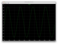
Looking pretty good so far.
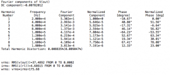
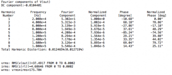
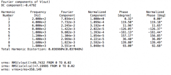
I had to tweak the comp to stop oscillations, but they do stop and we get decent thd, barely over 88ppm. Not too shabby!
Will take a peek at the ac analysis now...
I had to tweak the comp to stop oscillations, but they do stop and we get decent thd, barely over 88ppm. Not too shabby!
Will take a peek at the ac analysis now...
Attachments

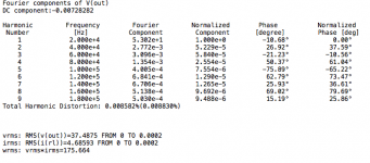
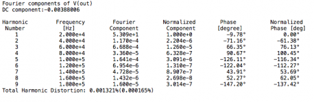
Tried equalizing the driver currents, but the trimmers don't have much effect and I couldn't get the wanted result. Tried with trimmers going both ways, but no matter what, the imbalance remains, with a little more current in the negative side.
However, despite the little imbalance there, after the tweak attempt, I looked at a transient analysis and wow! this actually brought down the thd a tiny bit more...
Go figure!
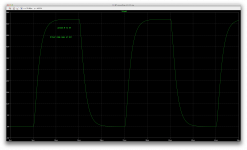
More to tweak and try, but this is well on the way. Less than 90ppm thd, not too bad for a first step. And we have this at 175W, full power before clipping, and we are at 20khz too.
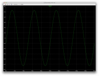
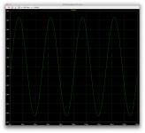
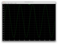
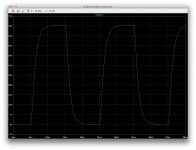
Good looking signal now.
However, despite the little imbalance there, after the tweak attempt, I looked at a transient analysis and wow! this actually brought down the thd a tiny bit more...
Go figure!
More to tweak and try, but this is well on the way. Less than 90ppm thd, not too bad for a first step. And we have this at 175W, full power before clipping, and we are at 20khz too.
Good looking signal now.
Attachments
With the compensation as it is now, we do have the gain spike, but it's well below unity gain and happening at about 4mhz. So nothing to worry about there, and that spike will move around a bit when tweaking the compensation.
Looks like we don't really need more, but we'll see what phase margin and other things show.
And at some point, when loading it with a complex speaker looking load instead of the plain 8ohms purely resistive, and feeding it square waves, we'll see then what else may be needed.
A good start for sure. I think.
Attachments
I've been reading through this thread, and a few comments:
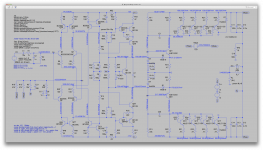
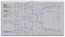
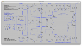
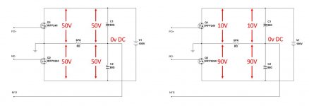
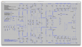
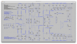
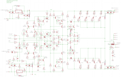
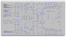
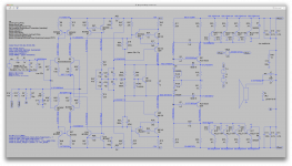
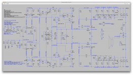
1: The reason you are having difficulty in getting LTspice to centre the power rails is that LTspice initially opens all capacitors and shorts all inductors, and then tries to establish the DC operating conditions. So if it removes the power supply capacitors, then there is no power to the output devices and so it cannot calculate the initial DC bias. You fix this by adding resistors (R6&R7) across the power supply capacitors (c1&c2) as per the attached diagram. Almost any value will do, so 10k is what I used. Whether a real amplifier would need these resistors I don't know, but I think I'd put them in.
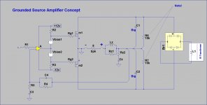
2: With regard to my simplistic concept amplifier attached, this type of amplifier works by voltage driving the output devices (mosfets in my case), which create a current to flow which finds its way around to drive the speaker `resistance' to create an output voltage. So the forward gain of the amplifier (and hence its loop gain) is the gain of the input stage (A), times the transconductance of the output devices (Gm), times the speaker resistance (what ever that may be). This causes a few problems, namely: The Gms of the two output devices are not likely to be the same, and vary with temperature and current. Then the speaker `resistance' is really a resistance, and if a crossover network is involved can be difficult to determine. The design of the zobel network is very important. Getting such an amplifier stable can be a real challenge!
3: Output stages that use CFP type arrangements can be difficult to make stable under all load conditions, and are prone to oscillate. I wouldn't try to use a CFP with this type amplifier.
4: The amplifiers used by ATC in their active speakers use this type of circuit, but have the advantage that an individual amplifier is used for each speaker, which is a known impedance (and always connected). Also the amplifier only handles those frequencies that the speaker can handle, each amplifier being preceeded by a band pass active filter.
If I haven't put you off at this point, I suggest that you try:
- adding resistors across the power supply capacitors,
- using a much simpler output stage and not a CFP (perhaps a pair of lateral mosfets),
- use a really simple input stage to get it going (LTP plus lender VAS and a few resistors) and increase its complexity once you have it all working.
regards,
Paul Bysouth
1: The reason you are having difficulty in getting LTspice to centre the power rails is that LTspice initially opens all capacitors and shorts all inductors, and then tries to establish the DC operating conditions. So if it removes the power supply capacitors, then there is no power to the output devices and so it cannot calculate the initial DC bias. You fix this by adding resistors (R6&R7) across the power supply capacitors (c1&c2) as per the attached diagram. Almost any value will do, so 10k is what I used. Whether a real amplifier would need these resistors I don't know, but I think I'd put them in.
2: With regard to my simplistic concept amplifier attached, this type of amplifier works by voltage driving the output devices (mosfets in my case), which create a current to flow which finds its way around to drive the speaker `resistance' to create an output voltage. So the forward gain of the amplifier (and hence its loop gain) is the gain of the input stage (A), times the transconductance of the output devices (Gm), times the speaker resistance (what ever that may be). This causes a few problems, namely: The Gms of the two output devices are not likely to be the same, and vary with temperature and current. Then the speaker `resistance' is really a resistance, and if a crossover network is involved can be difficult to determine. The design of the zobel network is very important. Getting such an amplifier stable can be a real challenge!
3: Output stages that use CFP type arrangements can be difficult to make stable under all load conditions, and are prone to oscillate. I wouldn't try to use a CFP with this type amplifier.
4: The amplifiers used by ATC in their active speakers use this type of circuit, but have the advantage that an individual amplifier is used for each speaker, which is a known impedance (and always connected). Also the amplifier only handles those frequencies that the speaker can handle, each amplifier being preceeded by a band pass active filter.
If I haven't put you off at this point, I suggest that you try:
- adding resistors across the power supply capacitors,
- using a much simpler output stage and not a CFP (perhaps a pair of lateral mosfets),
- use a really simple input stage to get it going (LTP plus lender VAS and a few resistors) and increase its complexity once you have it all working.
regards,
Paul Bysouth
Attachments
1: The reason you are having difficulty in getting LTspice to centre the power rails is that LTspice initially opens all capacitors and shorts all inductors, and then tries to establish the DC operating conditions. So if it removes the power supply capacitors, then there is no power to the output devices and so it cannot calculate the initial DC bias. You fix this by adding resistors (R6&R7) across the power supply capacitors (c1&c2) as per the attached diagram. Almost any value will do, so 10k is what I used. Whether a real amplifier would need these resistors I don't know, but I think I'd put them in.
Actually we no longer have that difficulty and instead of adding those resistors on the big caps, we used what is used in some commercial amps, which is that divider on the amp's input where the feedback comes back.
And I think it works because it's bleeding back through the feedback resistor to the speaker output, setting the op point and the issue is gone.
3: Output stages that use CFP type arrangements can be difficult to make stable under all load conditions, and are prone to oscillate. I wouldn't try to use a CFP with this type amplifier.
It works for qsc and the likes, and has for years. We just went for all bjt instead of using opamps. And I think although the part count is higher, this would be an easier build for diyers, with less tricky adjustments to get it going. I think opamps are very touchy and their high gains can sometimes cause wild oscillations when trying to build an amp, and before it's fully adjusted for bias, the risk is high to have issues. I think with bjts the risk is lower.
4: The amplifiers used by ATC in their active speakers use this type of circuit, but have the advantage that an individual amplifier is used for each speaker, which is a known impedance (and always connected). Also the amplifier only handles those frequencies that the speaker can handle, each amplifier being preceeded by a band pass active filter.
This could be interesting to look at other designs. I have heard of those and would like to see how they do things.
Have any links to point us directly to this relevant info?
Tried going up to 100k on the drivers feedback, and adjusting the small imbalance in driver bias.
Even with the adjusted trimmer values on their bases, it won't adjust.
However, with the previously adjusted compensation, we still have no signs of oscillations, although thd went up quite a bit.
I don't think we need to introduce more caps as it stands now...
But 100k doesn't bring any improvements.
Attachments

I've been reading through this thread, and a few comments:
1: The reason you are having difficulty in getting LTspice to centre the power rails is that LTspice initially opens all capacitors and shorts all inductors, and then tries to establish the DC operating conditions. So if it removes the power supply capacitors, then there is no power to the output devices and so it cannot calculate the initial DC bias. You fix this by adding resistors (R6&R7) across the power supply capacitors (c1&c2) as per the attached diagram. Almost any value will do, so 10k is what I used. Whether a real amplifier would need these resistors I don't know, but I think I'd put them in.
2: With regard to my simplistic concept amplifier attached, this type of amplifier works by voltage driving the output devices (mosfets in my case), which create a current to flow which finds its way around to drive the speaker `resistance' to create an output voltage. So the forward gain of the amplifier (and hence its loop gain) is the gain of the input stage (A), times the transconductance of the output devices (Gm), times the speaker resistance (what ever that may be). This causes a few problems, namely: The Gms of the two output devices are not likely to be the same, and vary with temperature and current. Then the speaker `resistance' is really a resistance, and if a crossover network is involved can be difficult to determine. The design of the zobel network is very important. Getting such an amplifier stable can be a real challenge!
3: Output stages that use CFP type arrangements can be difficult to make stable under all load conditions, and are prone to oscillate. I wouldn't try to use a CFP with this type amplifier.
4: The amplifiers used by ATC in their active speakers use this type of circuit, but have the advantage that an individual amplifier is used for each speaker, which is a known impedance (and always connected). Also the amplifier only handles those frequencies that the speaker can handle, each amplifier being preceeded by a band pass active filter.
If I haven't put you off at this point, I suggest that you try:
- adding resistors across the power supply capacitors,
- using a much simpler output stage and not a CFP (perhaps a pair of lateral mosfets),
- use a really simple input stage to get it going (LTP plus lender VAS and a few resistors) and increase its complexity once you have it all working.
regards,
Paul Bysouth
Paul, cool concept, with one important point to note. This is what I was trying to draw attention to throughout the thread and what is solved with the divider now 🙂
See the pictures (simplified arrangement). With floating supply, both cases are possible - it can float up and down in terms of DC. In both cases the OpAmp will "think" the system is balanced - we have zero volt at the output. So it will not correct the supply "moved" away from the center.
The divider gives the missing reference to the floating rails, "centering" them.
Cheers,
Valery
Attachments
Base stoppers
I'm reading other threads. In the thread on Bob Cordell's book, it was noted that current sources like ours can oscillate, and the simple cure is base stoppers. I'm thinking the same reasoning holds for the CFP Vas? At any rate, they cost almost nothing and out of an abundance of caution I'd suggest dropping them in. These don't address any topic we've been discussing, but are prudent precautions. I'll soon bring my schematic up to the level you are simulating, with that addition.
I'm reading other threads. In the thread on Bob Cordell's book, it was noted that current sources like ours can oscillate, and the simple cure is base stoppers. I'm thinking the same reasoning holds for the CFP Vas? At any rate, they cost almost nothing and out of an abundance of caution I'd suggest dropping them in. These don't address any topic we've been discussing, but are prudent precautions. I'll soon bring my schematic up to the level you are simulating, with that addition.
it was noted that current sources like ours can oscillate, and the simple cure is base stoppers.
We're not certain they do oscillate, but a little caution doesn't hurt.
I'm thinking the same reasoning holds for the CFP Vas?
That I'm not sure.
But there is one thing I also read about on other thread, is that higher values for the current mirror's degen res kill slew rate. But I don't think we need to worry about this for our low values there.
At any rate, they cost almost nothing and out of an abundance of caution I'd suggest dropping them in.
It needs what it needs. The part count can be a little concern, but if more parts make the amp better and stable, it must be done. The alternative isn't viable anyway.
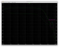
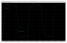
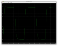
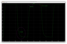
In the mean time, I was just trying for the first time to feed our amp with squares and see how it fares with regards to overshoots or eventual ringing.
For one thing, we have no ringing issues, so far (we'll see on complex loads)
We also have no real overshoot issue, although a little oddity before the falling edge is a little concern and we should eliminate that if we can.
One thing I can see is a rather symmetric slew rate, in the order of about 30V/us.
Not too bad, reasonably fast.
But the one thing that I think needs to be addressed is the lack of symmetry between the end of the rising and falling edges.
With a rather decent looking end of rising edge, but a rather "round" end of falling one.
This is an early test, just to see. As we're not quite done with everything yet. Once it's mostly stabilized and somewhat final, we can take a closer look at those odd behaviors and work towards improving them.
Attachments

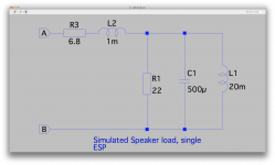
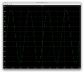
While I'm at it, I wanted to try it on a more complex load, and I have many different kinds of loads that emulate different types of speakers that could be encountered.
I tried it on a fairly simple one, that would be like a single speaker like a woofer or whatever.
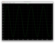
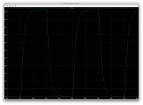
Sine wave looks clean and the funny thing is, thd drops by a bunch. How's that?
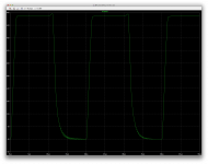
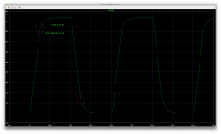
With the squares, we see the apparition of some oscillation at the problematic area at the end of the falling edge, in that rounded part that I thought should be addressed.
So there is something to fix, but nothing major. All this is probably fixable with compensation.
I tried it on a fairly simple one, that would be like a single speaker like a woofer or whatever.
Sine wave looks clean and the funny thing is, thd drops by a bunch. How's that?
With the squares, we see the apparition of some oscillation at the problematic area at the end of the falling edge, in that rounded part that I thought should be addressed.
So there is something to fix, but nothing major. All this is probably fixable with compensation.
Attachments
One more thing I wanted to look at is what happens when the zobel is moved to the speaker side of the coil.
It does changes things a bit. A slight overshoot appears at the end of the rising edge, and the small oscillations at the other end are still there but not on all periods. Odd.
The little peak right before the falling edge is there and I wonder what that really is.
It does changes things a bit. A slight overshoot appears at the end of the rising edge, and the small oscillations at the other end are still there but not on all periods. Odd.
The little peak right before the falling edge is there and I wonder what that really is.
Attachments
....
I did try it with the 47k divider before moving on the the 10k, so the currents could be compared. {interesting}
Do we need that much tail current in the current sources? {no, but it's working OK, is there a problem?}
Going to 10k also increases a little the ltp tail current, so each branch is now close to 3mA. {as intended, is there a problem?}
About my idea of combining the divider res in the sources tails into one. This wouldn't work if we need a tap for the cascodes, but perhaps it is still possible to combined the 2 in the middle and get off the ground tap. Perhaps the 2 caps could be one on the single res in the middle... {fine}
But I'm not sure it's good to have that much more tail current there. Is this for the cascode to use?
First, I'm happy that this is stable and has fairly good performance. Good fortune at last.
About your idea of combining the divider resistor, certainly, try combining the divider resistor if the combined resistor has some benefit. We have to revise the cascode base drive source. I only shared that divider with the cascode base drive because it was at about the right level and was such a low cost way to add cascodes to the VAS. If there is a separate string, I'd prefer a zener to set the cascode base voltage. Change it, evaluate it and hopefully it will be an improvement.
I did reduce the divider resistors to supply the additional base current for the cascodes, and of course that had the unintended consequences on the LTP current. Is that a concern? No problem to change if it improves things.
Let me explain the LTP current design choices. My main objective is that the LTP be very well balanced to minimize distortion, and the emitter resistors and current mirrors work extremely well to ensure excellent balance. The choice of unusually high tail current was deliberate (6ma or 3ma per side). At these low voltages, dissipation is not a limit, so higher current is no problem. My reasoning was that we need ample current to drive the VAS and its Miller cap, and large enough current so we do not imbalance the LTP due to the VAS load. The present CFP VAS has very low input current, but the Miller cap can demand high current at high frequencies. That was the thinking. It's not sacred, change it if you will and let's see if it does good or ill.
About the cascode, that's an experiment, so take measurements and let's evaluate the benefit. The EF buffer was not satisfactory to do what I wanted, so I reluctantly added parts for a cascode VAS. It provides a high impedance load to the VAS (so Miller compensation can be more effective) and it reduces the drive voltage to the driver, which seemed wise. So hopefully we get some performance improvement, and some protection for the driver.
I'm attaching a revised schematic. I added base stoppers everywhere. Separate base drive for the cascode.
I suspect the 1n cap on the drivers is the source of the asymmetry. Vary it, what happens? It's huge, but QSC used a larger one. Smaller value may speed up the downward edge, but may also bring back the oscillations. No free lunch.
Attachments
A simple fix for the oscillations on the squares and complex load.
Raising the miller caps from 10p to 15p stops them.
But I put the zobel back on the amp side though.
The symmetry is kind of better but not quite so good.
The small peaks at the start of the falling edge don't go away yet.
Amazingly there is a good amount of improvement at the end of the rising edge. Much sharper response, with no overshoot nor ringing.
Attachments

First, I'm happy that this is stable and has fairly good performance. Good fortune at last.
Yes, it seems well on the way to be good enough.
About your idea of combining the divider resistor, certainly, try combining the divider resistor if the combined resistor has some benefit.
Actually I tried already and it doesn't bring anything good for the cascode config.
It was positive for our previous config, just not so for the cascode.
We have to revise the cascode base drive source. I only shared that divider with the cascode base drive because it was at about the right level and was such a low cost way to add cascodes to the VAS.
I think it's fine this way. It was good without the cascode, but we can pass on this.
If there is a separate string, I'd prefer a zener to set the cascode base voltage. Change it, evaluate it and hopefully it will be an improvement.
If it is separate, it might get better that way...
I did reduce the divider resistors to supply the additional base current for the cascodes, and of course that had the unintended consequences on the LTP current. Is that a concern? No problem to change if it improves things.
It did have that side effect, although nothing major. But separating it might make it better, and we can then apply the part reduction on the current sources.
Let me explain the LTP current design choices. My main objective is that the LTP be very well balanced to minimize distortion, and the emitter resistors and current mirrors work extremely well to ensure excellent balance. The choice of unusually high tail current was deliberate (6ma or 3ma per side). At these low voltages, dissipation is not a limit, so higher current is no problem. My reasoning was that we need ample current to drive the VAS and its Miller cap, and large enough current so we do not imbalance the LTP due to the VAS load. The present CFP VAS has very low input current, but the Miller cap can demand high current at high frequencies. That was the thinking. It's not sacred, change it if you will and let's see if it does good or ill.
Ok. It looks fine I think and my only concern was in our previous config when the current in the 2n440x seemed rather high, which I thought in turn would load the ltp a little more than it could.
This may no longer be the case with the cascoded version though. I didn't add a data label on this. It's getting to look pretty good overall now, so I think we got things mostly under control.
About the cascode, that's an experiment, so take measurements and let's evaluate the benefit. The EF buffer was not satisfactory to do what I wanted, so I reluctantly added parts for a cascode VAS. It provides a high impedance load to the VAS (so Miller compensation can be more effective) and it reduces the drive voltage to the driver, which seemed wise. So hopefully we get some performance improvement, and some protection for the driver.
Seems to work well so far, but the adjustment on the driver bases still isn't functional.
I'm attaching a revised schematic. I added base stoppers everywhere. Separate base drive for the cascode.
Ok, that'll come next.
I just posted something and saw your last post. Some interesting results to look at.
I suspect the 1n cap on the drivers is the source of the asymmetry. Vary it, what happens?
I did before, and went up to 3n3 at some point, where I noticed it was getting worse there and a good value at the time seemed to be 2n2.
It's huge, but QSC used a larger one. Smaller value may speed up the downward edge, but may also bring back the oscillations. No free lunch.
This may be the reason for that slow response giving that rounded end to the falling edge. I will look at what happens with smaller values.
But once I had the miller and global comp worked out, it seemed to me that those caps on the drivers may not really be needed. So I'll try without as well.
Here are some results. I made all the changes, except for adding caps on the drivers emitter res.
And I used a 6V2 zener instead of 7V5 since those aren't in the ltspice library. This isn't a huge difference and may not interfere, or not much, but I can also look for an external model for that later on.
I also kept that simulated speaker load, since I had it there already, so I just kept going with it instead of switching back to the plain resistor load.
The sine still looks great, and thd looks quite good.
Since I was also doing some squares earlier, I did it again, and I had to up the value of the driver's 1n caps to 1n2 to stop small hints of oscillations at the end of the falling edge.
This looked rather good and I was still wondering about that little spike at the top, and then while posting this, I also realized one thing that is happening. The square wave I feed it starts at -1V5 and goes up to 1V5, but the output signal is all positive and isn't following to the negative part of it.
So then I thought maybe it was just clipping at the top, and that little spike may just be the resulting behavior of hard clipping.
And sure enough, reducing the drive to +/-1V got rid of that spike and the signal looks a lot more symmetric now, with the same rounded shapes at both ends of the rising and falling edges.
So the lack of symmetry isn't one, it was caused by the hard clipping, and so is that little spike.
I will post about this shortly.
But the one thing I don't understand yet is why a negative square part doesn't make it to the output...
Attachments

Here it is.
The ltspice pulse function isn't flexible enough as is so we can't get a square wave that goes from negative to positive the right way, so I had to limit this to one side only. But it behaves the same whether it's all positive or all negative.
The reason for that little spike was indeed due to hard clipping, so this must be a tiny bit of oscillation that appears when over driven hard. But we should never drive an amp that hard anyway... (or watch out speakers!!!)
It's not giving really square waves, but there is absolutely no ringing nor overshooting. Maybe a little slow on the ends of the edges.
I tried varying the driver caps, but they don't affect it a lot. We surely don't want any overly large values anyway, and as it is, 1n2 would be the minimum. I did try removing those caps, and small oscillations occur, so I put them back in.
Went up to 3n3 and we can see they don't really slow the response much to make the corners much rounder, and we only see some wiggles occurring with the large value, so better stay with the minimum of 1n2, which prevents all oscillations and there is no good reason to go any higher.
Adding caps on the driver emitter res doesn't do anything visible on the squares.
Attachments
One more thing I wanted to try, is if we really need that base network on the drivers.
Turns out, apparently we don't really do.
Once removed, there was hardly any difference, only a tiny bias adjustment to do and that's it.
Square doesn't look too bad, and sine looks great.
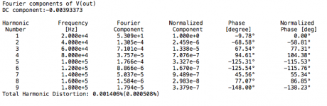
Look at thd, and we're at full power 175W on the fake speaker load, and at 20khz.
Turns out, apparently we don't really do.
Once removed, there was hardly any difference, only a tiny bias adjustment to do and that's it.
Square doesn't look too bad, and sine looks great.
Look at thd, and we're at full power 175W on the fake speaker load, and at 20khz.
Attachments
I know why the thd figures were looking so good in the last few sims.
That simulated speaker load being a woofer, and feeding it 20khz, makes for a high impedance and the amp is hardly loaded.
So I went down to 200hz and of course thd goes up quite a bit. Still fairly reasonable, but much higher than the few ppm...
I also figured I'd try one other thing we have not done yet, which is to up the rail voltage. So I went to 75V rails. Adjusted the bias. Everything still looks normal.
And sent it again the same 200hz. The input signal needs more umph to drive it, and I took it to a little before clipping, at 2V5.
Same thing with the squares. It takes the 2V5 to get about 70V peak. Squares look fair.
I'll have to try it on a different load that simulates a tweeter...
Attachments
Since we are thinking about simplifying the network feeding the current sources, can it be just one 47k-68k resistor from top to bottom source? Is there noise worth filtering out from the CCS? If so, a split resistor with a grounded cap in the center might do well. But if possible we should consider the single resistor..
Since we are thinking about simplifying the network feeding the current sources, can it be just one 47k-68k resistor from top to bottom source? Is there noise worth filtering out from the CCS? If so, a split resistor with a grounded cap in the center might do well. But if possible we should consider the single resistor..
That is what I tried and that equalized the currents, all the way to the front. Not completely of course, but it did bring things a little closer to balance.
And the thd went down along with it too, probably from having a better balance and the ltp tail currents being quite close to each other.
I didn't venture into the noise issue, since we are still working on so many other issues and making so many changes, the slightest thing can change the noise figures, so there was no point in analyzing noise figures that would be totally wrong with the next changes.
But we can take a closer look at that once we have finalized the schematic and values. Then perhaps if noise figures demand it, we can make a little bit more changes to address it.
If we're using very low noise transistors and try not to use overly large values in the resistors, noise figures shouldn't bother us much.
This amp doesn't have a whole lot of gain overall anyway, and especially with the change in closed loop gain that was done recently, that lower gain demands a higher signal at the input, and this lower sensitivity also should make noise a bit less of a concern.
In regards to that gain, it does take a stronger signal to bring it to full power, so a preamp needs to have enough headroom to drive it.
In P.A, this shouldn't be any concern, since a mix table might be driving the amp directly, or perhaps an equalizer in between which are usually line level and should drive this easily.
At line level, and with symmetric links, noise isn't major, and I doubt the amp would generate that much. But we'll see once we take a look..
- Status
- Not open for further replies.
- Home
- Amplifiers
- Solid State
- grounded collector amp