Brought back front end feedback split 680k
So what is that local gain now then? What other parts set that gain locally with those?
The concept of local feedback to reduce each stage's gain I think was proposed long ago by Matti Otala when he put forward the TIM distortion mechanism.
He then introduced local feedback to bring the gains to more moderate amounts and the global feedback loop was weaker. This method worked towards reducing the TIM and each stage was to be more linear.
In this case, perhaps there is too much local feedback, and maybe a little more gain should be allowed for a bit higher open loop gain.
As mentioned earlier, it's likely the global loop back does a lot to self center. So maybe a static centering by simple biasing may be a little beyond reach and the help of the gain from the closed loop might be the one that should force the rest of the way to center?!?!?
Does this make sense?
Reduced driver feedback resistor to 22K?
33k on your schematic. I tried both, and with 33k I had to tweak the values of the vas load res because we had a strong vas bias of over 70mA. I brought it down to more reasonable amount, but I had to increase the spreader's res to allow it to control the bias, or it would not affect it.
It probably still could drop some more, but would that make it a little too weak in regards to the driver's loading?
Now tried with 22k feedback res and I tried upping much more the spreader's res, and I gave up at a 47k trimmer, because although it probably have been able to drop the O.D's bias closer to what we want, I think it would've taken a lot bigger value and that's probably not desirable.
I noticed how rather strong the base current is on the vas trannies. And that point to them having a current gain of only in the order of 5. Is this right?
Changed 22 ohm to 8 100 ohm resistors. Equalize effect.
Right. That was my thinking. If you really need to tap there, all pairs should be involved. More part count, but nothing to worry about. Balance is better.
Attachments
Just for kicks, I removed the global feedback tap from the speaker output, to show what happens then to the voltage there.
Pretty darn close to 0V, and this happens no matter what the rails are doing, dc wise of course.
I'm guessing the tiny voltage that is present must be due only to some leakage in the filter caps, which the models probably are addressing...
Pretty darn close to 0V, and this happens no matter what the rails are doing, dc wise of course.
I'm guessing the tiny voltage that is present must be due only to some leakage in the filter caps, which the models probably are addressing...
Attachments
Oh, and by the way, that little "experiment" of removing the global feedback tap from the output, seem to point out what role the global feedback has on the rail centering.
It is putting in evidence that without it, as it is right now, the rails stick all the way up, and closing the loop does bring it much closer to center.
So the centering that we have is not really fully set by biasing, but much more by the feedback forcing the centering...
Something to ponder...
It is putting in evidence that without it, as it is right now, the rails stick all the way up, and closing the loop does bring it much closer to center.
So the centering that we have is not really fully set by biasing, but much more by the feedback forcing the centering...
Something to ponder...
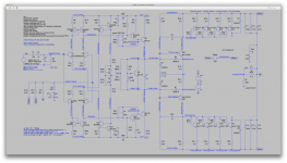
Alright then, here you go. This is the latest up to a few posts ago, as I just zipped this up and haven't yet tried the latest changes.
Hopefully everything should work out of the box, if I didn't leave out a stray model...
Thanks 🙂
I'll have a look and play later all being well.
Hmmm....
I'd kept looking at this and had an idea. The reason the current in the output stage is always balanced is because the two halves are just a series circuit across the floating supply. The ground point is arbitrary.
I had the Quad single rail 606 in mind which uses a simple rail balancing technique. I thought that might work here if the centre point of the balancer was moved to the midpoint of the reservoir caps rather than ground.
Does this do the trick ?
It seems balanced for any value of Iq you dial in.
(the preset and IN4001's didn't work model wise and so I snipped them out)
Attachments
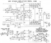
As I mentioned somewhere close to the beginning of the thread - think about the rails reference. As an example, QSC is getting +/-15V for the front-end right from the main rails (those are floating - that's fine) - using R + Zeners.
In you case, from what I can see, +/-15V rails are referenced to ground, however the floating main supply does not have any mechanism for balancing itself in terms of DC - neither referenced to ground, nor references to those +/-15V. Or I don't see it 🙂
In you case, from what I can see, +/-15V rails are referenced to ground, however the floating main supply does not have any mechanism for balancing itself in terms of DC - neither referenced to ground, nor references to those +/-15V. Or I don't see it 🙂
A basic transient simulation of the amp is a bit odd. At a basic level its OK, but as soon as I add .options maxstep=0.48831106u to the sim the whole amp oscillates 
As I mentioned somewhere close to the beginning of the thread - think about the rails reference. As an example, QSC is getting +/-15V for the front-end right from the main rails (those are floating - that's fine) - using R + Zeners.
In you case, from what I can see, +/-15V rails are referenced to ground, however the floating main supply does not have any mechanism for balancing itself in terms of DC - neither referenced to ground, nor references to those +/-15V. Or I don't see it 🙂
I don't believe the rails for the non floating front end must be tied in any way to the floating rails. Actually even when the power is tapped from the floating rails to make up the non floating ones for the opamp, those opamp power rails don't float.
When the main rails float, there is a point when the non floating rails' zeners are reversed biased and besides a couple of diodes there to prevent this from going to far, there is only the cap in parallel with that zener that can delay the depletion of the non floating rails while the floating ones swing below them.
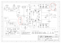
I outlined a relevant part of that schematic from ram audio's ma series amp, as the one posted at the beginning of this thread, where they have a resistive divider between the rails to generated that virtual half way point, and they feed that right into the return from the feedback, which is what must be holding the center for the amp.
The opamp has high gain and negligible input current, so this virtual mid point won't be swinging much from its intended target.
With a bjt front end, we don't have such a high gain, but perhaps we should aim at maximizing that and perhaps use a similar method to force that centering.
Attachments
A basic transient simulation of the amp is a bit odd. At a basic level its OK, but as soon as I add .options maxstep=0.48831106u to the sim the whole amp oscillates
Well, we do know it's rather unstable for now. All the focus has been more into getting proper operating point with the rails properly centered.
I did have it run with decent thd and clean signal at some point, although without sufficient phase margin and the square signals didn't look good enough.
It can work. We'll get this worked out somehow.
I haven't tried simulating that ram audio amp, but maybe that one won't be giving as much trouble to simulate as the qsc one.
Spookydd said: With a bjt front end, we don't have such a high gain, but perhaps we should aim at maximizing that and perhaps use a similar method to force that centering.
I say: We can give it a shot. I will clone the feedback network from a QSC1400 version. They do use an op amp so this might not work.
I say: We can give it a shot. I will clone the feedback network from a QSC1400 version. They do use an op amp so this might not work.
Attachments

Last edited:
It seems DC stable now with the addition of a balancer.
The circuit is a little erm... enigmatic shall we say... but I had a play and trimmed it down a little.
I see it gets much closer to balance this way, but not 100%, and perhaps it needs a adjustment, but that brings one more trimmer.
This seems somewhat stable just like what I had before and got fairly decent thd, but the phase margin just isn't there and I can see the thd rises sharply with signal strength and frequency.
Maybe something to continue exploring.
Spookydd said: With a bjt front end, we don't have such a high gain, but perhaps we should aim at maximizing that and perhaps use a similar method to force that centering.
I say: We can give it a shot. I will clone the feedback network from a QSC1400 version. They do use an op amp so this might not work.
I did see that 1400 models before, but I didn't recall their use of that divider to force the centering. And they even have a trimmer there, but it's not dc coupled, so I'm puzzled as to what it real use is.
The real question is will it have all the effect we need, since we're feeding this in a bjt ltp and not an opamp. With the fet inputs in the opamps, the very high impedance probably allows better control.
But we'll see what the simulations say. I'll work on this later on, as I have to be away now for a while...
Spookydd said: With a bjt front end, we don't have such a high gain, but perhaps we should aim at maximizing that and perhaps use a similar method to force that centering.
I say: We can give it a shot. I will clone the feedback network from a QSC1400 version. They do use an op amp so this might not work.
That divider - R2, R3 on your schematic - provides the reference point that's been missing all the time. This is the only point, giving the information (feedback) on where the floating supply is, referenced to ground, in terms of DC, so that the front-end can generate the offset for centering it.
Spookydd said: With a bjt front end, we don't have such a high gain, but perhaps we should aim at maximizing that and perhaps use a similar method to force that centering.
I say: We can give it a shot. I will clone the feedback network from a QSC1400 version. They do use an op amp so this might not work.
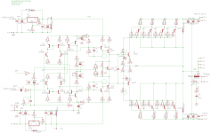
Amazing!!!
I wanted to share this shot before I did any tweaking.
I just finished making the changes, double-checked for mistakes, which for now seem absent, and then I just gave it a whirl with the bias trimmer as it was earlier and the extra centering trimmer right on center, and bam!
bias is way too high, it's not adjusted, and I can see that a higher value at the bias trimmer will be needed to bring the bias down to reasonable value, since it's just about at maximum now.
But hey, it's pretty damn close to exactly balanced ain't it?
I know that adjusting bias usually affects the centering, but perhaps this time it won't, because what makes it balanced should logically continue to do so with a different bias set up.
One thing seems out of range though, the bias in the vas, seems too strong. I will check on the vas trannies' dissipation, but I'm pretty sure this is limit...
Attachments
Alright then, after adjusting the bias, I took a reading of idle dissipation in one of the vas tranny, and it's a little less than 5mw, so I guess within the capacity of those BDs, but do we need it that high?
It took a much higher value for the bias trimmer to bring that bias current down to "normal", and during the adjustment, as I thought it would, the centering wasn't affected, so I guess we got that centering issue tamed now. One nice shot in the right direction.
I'm thinking that with such a heavy vas bias current, as I'm seeing how high it is as well in the trannies driving the vas ones, that perhaps we're loading the ltp quite a bit. Should this be avoided?
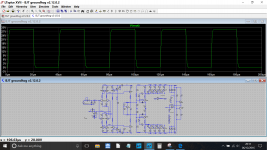
Just to see how it fares, I ran a transient analysis, and as is it does oscillate, but not as hard as we had it before. This seems more even and I think controllable.
I didn't have a compensation cap on the feedback, so it's likely it will need one. As all we have are the miller and the ones on the drivers to compensate.
Not sure what those caps will bring on the drivers...
But there are options to explore.
Now that it centers, I think it's well on the way.
It took a much higher value for the bias trimmer to bring that bias current down to "normal", and during the adjustment, as I thought it would, the centering wasn't affected, so I guess we got that centering issue tamed now. One nice shot in the right direction.
I'm thinking that with such a heavy vas bias current, as I'm seeing how high it is as well in the trannies driving the vas ones, that perhaps we're loading the ltp quite a bit. Should this be avoided?
Just to see how it fares, I ran a transient analysis, and as is it does oscillate, but not as hard as we had it before. This seems more even and I think controllable.
I didn't have a compensation cap on the feedback, so it's likely it will need one. As all we have are the miller and the ones on the drivers to compensate.
Not sure what those caps will bring on the drivers...
But there are options to explore.
Now that it centers, I think it's well on the way.
Attachments

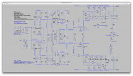
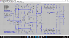
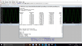
I have it stabilized and I was underestimating the available phase margin.
I added a tian probe and we have a nearly 50 degrees of phase margin. Although the phase margin seems right, the gain margin isn't, as it should be positive and it isn't.
So something needs to be tweaked to get this working better.
Now going on my hunch about the excessive loading on the ltp, I tried lightening it up and doing so improved the phase margin even more, about 6 degrees or so, and the gain margin also improved but not enough yet.
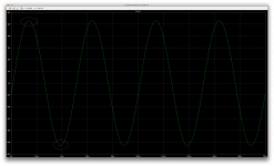
There is one issue though, that is there no matter what. Look at the screenshot, there are little notches at each peak of the sine wave, kind of like a gentle clipping, which appears at just about any voltage level, so it really isn't clipping, as it's there way below the clip level.
What could be the origin of such a behavior? Maybe someone will recognize this and point right to the source of it.
I did add a global feedback cap, and both that and the miller caps are 22p. Left the cap on the drivers at 1n, but there may be some tweaking to do there to improve things some more.
One other detail, we had moved the zobel to the amp's output from the speaker end of it, and when I moved it back before the output coil, the phase margin gained about 2 more degrees.
qsc is putting it there in their amps, maybe they have a reason...
Other than those issues, it's centering just fine, no matter what the bias, which no longer has any effect on it.
Perhaps the issue with the notches on the peaks will go away once the gain margin gets better at the same time. Just wishful thinking...
I added a tian probe and we have a nearly 50 degrees of phase margin. Although the phase margin seems right, the gain margin isn't, as it should be positive and it isn't.
So something needs to be tweaked to get this working better.
Now going on my hunch about the excessive loading on the ltp, I tried lightening it up and doing so improved the phase margin even more, about 6 degrees or so, and the gain margin also improved but not enough yet.
There is one issue though, that is there no matter what. Look at the screenshot, there are little notches at each peak of the sine wave, kind of like a gentle clipping, which appears at just about any voltage level, so it really isn't clipping, as it's there way below the clip level.
What could be the origin of such a behavior? Maybe someone will recognize this and point right to the source of it.
I did add a global feedback cap, and both that and the miller caps are 22p. Left the cap on the drivers at 1n, but there may be some tweaking to do there to improve things some more.
One other detail, we had moved the zobel to the amp's output from the speaker end of it, and when I moved it back before the output coil, the phase margin gained about 2 more degrees.
qsc is putting it there in their amps, maybe they have a reason...
Other than those issues, it's centering just fine, no matter what the bias, which no longer has any effect on it.
Perhaps the issue with the notches on the peaks will go away once the gain margin gets better at the same time. Just wishful thinking...
Attachments
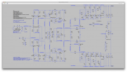
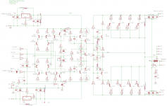
I'm changing very little, only values to allow us to bring currents to target.
OK, there is one correction, adding a missing collector load resistor for the 2N440X transistors. The EF buffers need this. It will have an effect on current in the EF and other ripples, so adjustments may be needed.
I upped the collector loads for the EF to 330 from 220, not sure if that is needed after correction just mentioned.
I changed the bias spreader divider to pots, so you put the values needed.
I changed the driver base resistor pots to two pots, to let you set the quiescent current in the driver to about 30ma and hopefully the outputs to 50-100ma.
As for the notch on the top of the sine wave, another black hole. Nothing is obvious. Well, let's put in these hopefully minor changes and take another look.
Attachments
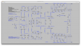
I'm changing very little, only values to allow us to bring currents to target.
Not enough yet.
For reference, when I tried earlier to reduce that high vas bias current, I upped the vas load res to 680, and at the same time upped the 2n440x load res to 470, which reduced loading on the ltp and perhaps that's where the betterment of the phase margin come from... (anyone confirm this?)
From about 70mA of vas bias, I dropped it to about 22-23mA, and the drivers were at about 32-33mA.
I mentioned the dissipation of a bit less than 5mw in a vas transistor, but this had to be wrong, I don't know why it gave that reading, but that seemed very much understated in regards to the current passing through there.
Now it's giving something that seems far more believable at close to 800mw, with some 46mA passing through, and I think this definitely would require heatsinking... But maybe we don't really need quite that much there.
OK, there is one correction, adding a missing collector load resistor for the 2N440X transistors. The EF buffers need this. It will have an effect on current in the EF and other ripples, so adjustments may be needed.
That helped a bit, but not enough, as you can see that vas bias still over 46mA. I think we can drop that down some more.
With this high current in the vas, even with higher res values in the spreader, it's hard to drop the bias in the O.Ds, and the drivers are at twice as much as we target, and even a bit more.
I upped the collector loads for the EF to 330 from 220, not sure if that is needed after correction just mentioned.
More is needed. 680 works. with more on the 2n440x as well.
I changed the bias spreader divider to pots, so you put the values needed.
I just change the values there. In the sim that works faster.
I changed the driver base resistor pots to two pots, to let you set the quiescent current in the driver to about 30ma and hopefully the outputs to 50-100ma.
I couldn't adjust much that way, probably just because of the overly high bias.
As for the notch on the top of the sine wave, another black hole. Nothing is obvious.
Well, after solving that centering issue, I think this shouldn't be any harder.
Attachments
- Status
- Not open for further replies.
- Home
- Amplifiers
- Solid State
- grounded collector amp