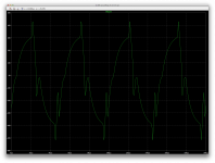
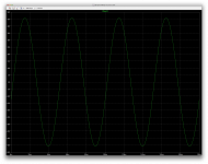
Before tweaking any values, other than those getting the last dc op point, I gave it a whirl with transient, and this ain't so pretty so far.
But haven't tweaked anything yet.
But haven't tweaked anything yet.
Attachments
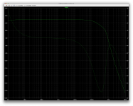
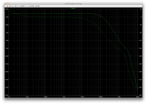
With the slower mj15003/4, we see in the ac analysis that the gain spike would appear at much lower frequency and it's almost all obscured with the limited compensation in place as it is now.
What I find odd is that looking at the phase response, the margin would be always way above 100 degrees that way, and yet, look at the oscillating sine!
Will try other things...
What I find odd is that looking at the phase response, the margin would be always way above 100 degrees that way, and yet, look at the oscillating sine!
Will try other things...
Attachments
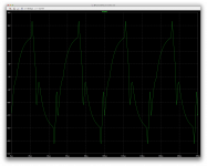
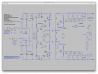
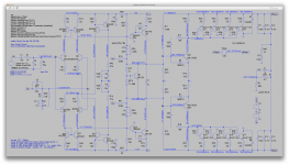
Unstable!
We didn't have any global feedback cap for some time, and without one we get those huge oscillations as in previous shots.
I tried caps in various positions, but only the global feedback one can curb most of those oscillations, but nowhere near completely.
That global feedback cap needs to be about the 22p as shown, or anything too big or smaller gets more oscillations.
The R/C on the drivers doesn't do diddly. With or without, it's basically the same.
The miller caps need to be at least 180p to show this somewhat resembling sine wave, but smaller gets larger oscillations.
We may have some kind of somewhat a little off center operating point, but it's not operational yet.
Attachments

Sorry, I meant like QSC, slow outputs. Fast drivers. Trying to mimic a working design.
Ooops! Yes, sorry I was fixated on those drivers...
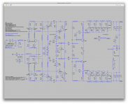
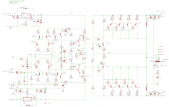
Well, reverting to the mje drivers and swaping the 1302/3281 for the mj15003/4 makes a lot of difference.
And we can see how the differences in the models can change things a lot, because now it's the npn side having bias current higher than the other. We always had a higher bias on the pnp side with the 1302/3281, no matter what was used as drivers. Interesting to note.
Obviously the imbalance of the rails is caused by those differences.
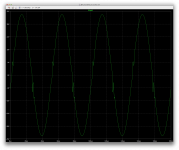
We do have an imbalance, still, but I can stabilize it for a clean sine wave.
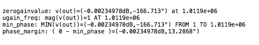
However, I'd like to understand certain things. If I tweak the compensation for a good phase margin, this thing oscillates. I was able to get a phase margin, insufficient, but a good start, at a little more than 18 degrees (see plot).
However, with the highest phase margin obtained, it oscillates and the sine wave is quite ugly.
If I aim at cleaning up the signal, the phase margin worsens, but then all oscillations go away and we even get a fairly decent thd.
I will post shots of that in the next post.
I didn't need using the R/C on the drivers. They didn't bring any better stability and worsened the thd.
The comp caps values need not to be too big, not just for better thd, but also they allow oscillations with overly high values, so we can't gain more margin from that.
Since the rails aren't quite balanced, we won't get best performance either, at least not full power, as it will start clipping on one side first, and well before the other.
Good thing is, it seems to be able to be made stable. Slower O.Ds help in this case.
Attachments

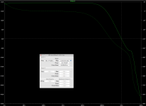

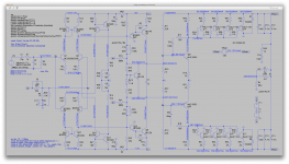
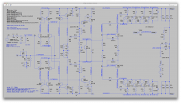
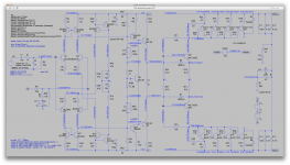
Ok. In the previous post, I was aiming for a reasonable phase margin, and although I managed to get some, which was insufficient, the transient analysis revealed a serious case of oscillation.
You can notice the small bump where the gain spike is hiding, and when it's there, we have oscillations, even though some phase margin is there.
Now when shooting for stability and at the expense of some phase margin, we can see the spot where the gain spike would be almost smooth, and no signs of oscillations, low(ish) thd, but less margin.
That's what I'd like someone to explain. How can we have oscillations with better margin and none with worse margin? Beats me!
Anyway, the tweak done here drops the phase margin down around 13 degrees, but no oscillations.
Of course with the rail imbalance, I had to reduce the input signal to prevent clipping, so we do get lower power out. And if we push it a little more and it starts clipping, then come loads of oscillations. So we do not want to let it clip much for sure.
More tweaking needed, but this is coming together, I think.
Attachments
-
 Screen Shot 2016-12-03 at 11.42.32 PM.png38.1 KB · Views: 74
 -
 Screen Shot 2016-12-03 at 11.42.18 PM.png253.9 KB · Views: 68
 -
 Screen Shot 2016-12-03 at 11.41.00 PM.png19.8 KB · Views: 61
 -
 Screen Shot 2016-12-03 at 11.40.49 PM.png264.8 KB · Views: 72
 -
 Screen Shot 2016-12-03 at 11.41.39 PM.png690.9 KB · Views: 88
You are an optimist. There is a ghost in the circuit, waiting to cause oscillations whenever you fix something. That's how it feels.
About the outputs, interesting that the slow ones change matters. Looking at the available slow ones, I suggest we use mj21193/4s which are just as slow, rather robust, and in plastic packages. Just a suggestion if you have the model.
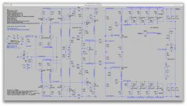
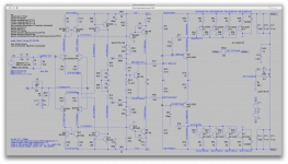
Looking at the schematic you posted, what happens if we remove the 100 ohm resistors to the driver bases? Would that help centering? Tighter coupling should help.
About the outputs, interesting that the slow ones change matters. Looking at the available slow ones, I suggest we use mj21193/4s which are just as slow, rather robust, and in plastic packages. Just a suggestion if you have the model.
Looking at the schematic you posted, what happens if we remove the 100 ohm resistors to the driver bases? Would that help centering? Tighter coupling should help.
You are an optimist. There is a ghost in the circuit, waiting to cause oscillations whenever you fix something. That's how it feels.
Well, at least it does work and oscillations can be stopped. I even had to seriously increase the output coil's value to gain some margin. But it's true it's not close enough to fully stable. For one thing, when clipping, it does go into serious oscillations, and then what happens on complex reactive loads remains to be seen.
About the outputs, interesting that the slow ones change matters. Looking at the available slow ones, I suggest we use mj21193/4s which are just as slow, rather robust, and in plastic packages. Just a suggestion if you have the model.
Yes, I've seen this in many simulations, where slower devices are the only way to make it work.
The mjl version of the 21193/4 are the plastic version. Those are so very popular, we do have models. And those are even in our friend guru cordell's library, so of course we have them and I'll give them a try.
Looking at the schematic you posted, what happens if we remove the 100 ohm resistors to the driver bases? Would that help centering? Tighter coupling should help.
Logically it should, but who know? Sometimes things don't turn out as we expect. I'll post shortly the results on this.
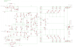
Using those beefy mjl21193/4 gives the bias spreader a harder time at "pinching" the driver's bases, so I had to revamp the spreader's values to make it go.
Since upping some values there caused a drop in vas bias current, I also had as a result to drop a little bit the vas load res value, to get back to roughly the same bias current passing through that branch.
I also upped the driver's base res a little, or the spreader doesn't adjust well enough. This may make it harder to center, but we'll see.
It must be the lower gain in those big O.Ds that causes this little difficulty.
With those few little changes, I got a bias set, but the rails are stuck all the way up though, so no luck there.
No need to bother trying a transient sim for sure.
Attachments
It seems like the output stage is dominating. The DC feedback current is completely swamping the front end's control voltage. Try increasing the 22k resistors in the DC feedback to 47k or higher to lessen that. We had 100k before and it worked OK. I also reduced the driver emitter resistors to 6.8 ohm, and may revert to the original 4.7 ohm.
Regarding behavior at clipping? Not sure what's going on there, and it's down the list in importance right now. I'd like to get this centered, and stable. But, remember the diode I had reversed across driver base emitters? It was to protect the off side driver. When reverse biased heavily, it does not act as a transistor and can fail. We have to clamp it. We may also want to reduce the drive current, by decreasing the VAS current. I show 100 ohm at the VAS emitter as a trial.
I am also reducing the fixed gain of the front end to 5 by reducing the 680k resistors to 330k. I just want to keep the front end centered regardless of the output load.
Attachments
It seems like the output stage is dominating. The DC feedback current is completely swamping the front end's control voltage. Try increasing the 22k resistors in the DC feedback to 47k or higher to lessen that. We had 100k before and it worked OK. I also reduced the driver emitter resistors to 6.8 ohm, and may revert to the original 4.7 ohm.
The main issue remains the centering.
It's actually worse with the higher value res, and effectively stuck all the way up with the 100k.
I reverted the driver base res to 470 as we had earlier. No values shown on your schematic.
Haven't tried with the even lower res values on the driver emitters yet. But this may not change things that much.
Regarding behavior at clipping? Not sure what's going on there, and it's down the list in importance right now. I'd like to get this centered, and stable.
Well I think this goes together. It's not stable enough, nor centered, so when clipping, it's no surprise it doesn't behave right.
But, remember the diode I had reversed across driver base emitters? It was to protect the off side driver. When reverse biased heavily, it does not act as a transistor and can fail. We have to clamp it.
Perhaps that may also have contributed to the bad clipping behavior. Fortunately, we can cause all kinds of havoc in the sims, and there is no real silicon to burn up... 😀
We may also want to reduce the drive current, by decreasing the VAS current. I show 100 ohm at the VAS emitter as a trial.
Reverted to the simpler res network on the spreader base for that. We have a vas bias dropped to 9-10mA.
What I find amazing is how the bias is very closely the same even though it's totally stuck on one side. With very low voltage on the V- side, it still manages to draw the same bias as the opposite side.
I am also reducing the fixed gain of the front end to 5 by reducing the 680k resistors to 330k. I just want to keep the front end centered regardless of the output load.
Ok.
Now it needs something more to get it centered.
Attachments

We have a huge offset at the output emitters. We have almost zero offset voltage at the output. The front end is doing its job, but the output stage is wildly asymmetric. The high and low output sides behave very differently because the complementary transistors are really quite different.
I'll try to equalize them more with a different local feedback scheme on the output stage.
I'll try to equalize them more with a different local feedback scheme on the output stage.
Attachments
It seems like the output stage is dominating. The DC feedback current is completely swamping the front end's control voltage.
Seems like you don't have enough open loop gain to do the necessary correction. The output stage has a relatively low input impedance. That's a pretty heavy load on the vas - giving that stage a relatively low gain. Doesn't need much output voltage swing, but you do want gain. In most implementations, an op amp is used for the front end and one reason for that is the low z output. And the fact that the op amp is already unity gain stable so the overall loop can afford the output stage gain and still be stable.
If the vas has a low gain, miller comp won't work. You won't get the pole splitting effect and the non dominat poles start to eat your lunch. It may be more stable by adding an EF stage to the front end before it drives the MJEs.
wg_ski said: ...you don't have enough open loop gain to do the necessary correction. The output stage has a relatively low input impedance. That's a pretty heavy load on the vas - giving that stage a relatively low gain. Doesn't need much output voltage swing, but you do want gain....
I say: OK. I put an EF buffer on the output. I opened up the gain. Who knows, might help.
I say: OK. I put an EF buffer on the output. I opened up the gain. Who knows, might help.
Attachments
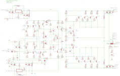
Is there a .asc file anywhere to play with ?
🙂
Of course, we sure do, since I'm doing those sims. I just make it simpler and faster for me by just posting screenshots, but I'll gather the files, zip them and post what we have currently.
We have a huge offset at the output emitters. We have almost zero offset voltage at the output.
Well the only offset possible on the output is whatever the feedback loop sends back. If you disconnect the feedback, then we end up with something in the femto-volts there, even if the rails are totally stuck one way or the other. Remember the output is only made through those big filter caps, so since it's capacitive coupling, no dc can make it through.
So you can't base anything on the output offset, only on how the rails relate to ground.
The front end is doing its job, but the output stage is wildly asymmetric. The high and low output sides behave very differently because the complementary transistors are really quite different.
That is exactly what we're battling. And we can't be fixing this by making the models more agreeable, as this is not what we have in the real world.
So this should be able to deal with whatever differences are there in the real parts, which is kind of what the models emulate by not being the same.
I'll try to equalize them more with a different local feedback scheme on the output stage.
I wonder how it works on those qsc amps.
Is there a .asc file anywhere to play with ?
🙂
Alright then, here you go. This is the latest up to a few posts ago, as I just zipped this up and haven't yet tried the latest changes.
Hopefully everything should work out of the box, if I didn't leave out a stray model...
Attachments
I'll try to equalize them more with a different local feedback scheme on the output stage.
Keep an eye on the emitter bias current in the O.Ds, doing this makes one pair hotter than the other 3.
Anyway, it's not going all the way full swing, but still swings hard, although a bit less than our last attempt.
Attachments
wg_ski said: ...you don't have enough open loop gain to do the necessary correction. The output stage has a relatively low input impedance. That's a pretty heavy load on the vas - giving that stage a relatively low gain. Doesn't need much output voltage swing, but you do want gain....
I say: OK. I put an EF buffer on the output. I opened up the gain. Who knows, might help.
I hope I didn't leave anything out, but it won't center and bias won't come to a reasonable amount. I increased the bias trimmer a bunch and went even higher, to gain almost nothing more.
The bias current in the vas went down quite a bit now, maybe not enough to drives this and control the bias down the road.
Needs a few more adjustments.
Attachments
- Status
- Not open for further replies.
- Home
- Amplifiers
- Solid State
- grounded collector amp