If you are right then you need two isolated channels. That requires 4 secondary windings, or two centre tapped windings.
Thanks for the link.
Centre tap is not connected, you need two 80vac secondary windings for two channels.
Does that mean it's a virtual ground inside a floating PSU?Centre tap is not connected, you need two 80vac secondary windings for two channels.
Where does one make the Safety connection to the Chassis to make all the exposed metal parts safe to touch?
Does that mean it's a virtual ground inside a floating PSU?
Where does one make the Safety connection to the Chassis to make all the exposed metal parts safe to touch?
There is no virtual ground, amplifier output is connect to the ground and speaker output floating, PSU is not connected to the ground. Amplifier topology is common emiteur output stage so collectors is amp out and collector is connected to heatsink without insulators, heatsink is connected to the chassis.
The junction between the two big caps looks like a virtual ground to me. And the speaker is connected to heatsinks.
You are confirming that the "floating amplifier" gets it Safety connection from the heatsink and output stage collectors.
You are confirming that the "floating amplifier" gets it Safety connection from the heatsink and output stage collectors.
hello
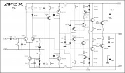
This is a stereo version of apex ax17 for a living room amp i'm making. My compliments to apex audio for the schematic. This module was already tested and is working wonderfully.
Can anyone provide me with some higher resolution apex logos for me to incorporate onto the pcb. Aside from the test pcb above, i'll be making some other boards (another stereo board, some psu and protection boards) and want to place that logo on them.
I would like to make a separate board for the short circuit/overload protection circuits for this amp. I've seen some different designs for this, has anyone tested them with ax17. Any recommendations pls?
An externally hosted image should be here but it was not working when we last tested it.
hello
This is a stereo version of apex ax17 for a living room amp i'm making. My compliments to apex audio for the schematic. This module was already tested and is working wonderfully.
Can anyone provide me with some higher resolution apex logos for me to incorporate onto the pcb. Aside from the test pcb above, i'll be making some other boards (another stereo board, some psu and protection boards) and want to place that logo on them.
I would like to make a separate board for the short circuit/overload protection circuits for this amp. I've seen some different designs for this, has anyone tested them with ax17. Any recommendations pls?
An externally hosted image should be here but it was not working when we last tested it.
Nice work, you can use FX100 PSU with protect from thread:
http://www.diyaudio.com/forums/solid-state/162081-dc-servo-mosfet-amplifier-61.html#post4624521
Regards
fixed the image, it was not zooming correctly. There is a third trimmer resistor for gain and r21 was increased to 1.5k for easy bias adjustment. For added oumph 4 output transistor pairs are used per channel. The L bracket aluminum piece connects to a larger heatsink.
I'll be using the fx100 psu and maybe add some fan control. Thank you.
Bogdan
An externally hosted image should be here but it was not working when we last tested it.
image hosting over 5mbI'll be using the fx100 psu and maybe add some fan control. Thank you.
Bogdan
Hi all, i want to make this low pass filter. Has anyone the pcb for this project? I`ts very simple for me to make it. Thanks in advance and sorry for my english.
http://i64.tinypic.com/9i9pqf.jpg
http://i64.tinypic.com/9i9pqf.jpg
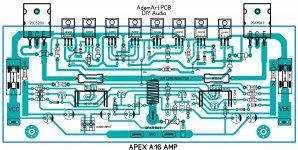
hi sir apex here is your A16 amp i try to layout PCB sorry for possible error correct me if i am wrong I'm still learning
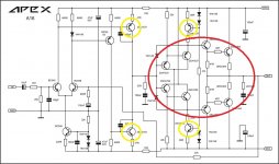
Nice work but all 2SA and 2SC transistors must be on main heatsink... this is schematic with correct 56R instead 560R.
Regards
Attachments

Last edited:


ok sir thank you i will make PCB layout again 2SA and 2SC transistor to be fix on heatsink and thanks for those correction of 56R resistor
Hi Miles, could you advice about what transistor must be on heatsink please?
Marc
Yelow on heatsink and Red on main heatsink.
Regards
Attachments
hello sir apex may be like this layout? all 2SA 2SC transistor mounted in heat sink except those 2 separated from main heat sink hope no error.. I'm still learning electronics
Nice pcb, LTP BC546 can be thermaly coupled, what is pcb size?
Regards
Hello Sir Mile, where i can find dc speaker protect with rellay for ax16?
Sent from my Coolpad 8297W using Tapatalk
Sent from my Coolpad 8297W using Tapatalk
- Home
- Amplifiers
- Solid State
- 100W Ultimate Fidelity Amplifier