Hi Alex,
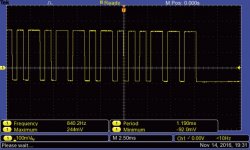
The resistor is 100 ohms... I take another waveform that should looks more clean
I tried other remotes and also to reprogram the remote.
The wave form is the same for all what I tried.
The +V is 3.18V. The output is normally high at 3.16V and drop at 1.8V when I send the signal.
I also rechecked the ARM but everything seems ok...I can't figure out where is the problem
Thanks and Regards,
Enrico
Attachments
Hi Enrico,
Why the signal does not drop to 0? That is the problem, a 0 won't be detected.
What is your UcBoard PCB revision?
Why the signal does not drop to 0? That is the problem, a 0 won't be detected.
What is your UcBoard PCB revision?
Ok then no problem this is the right version, V1.1 has a different pinout but nobody has some except me.
They work perfectly fine as well just the MCU pinout is a bit different so for a minute I had a doubt.
But I never shipped any so no worries.
Still I don't understand why the level is 1.8V or a logical 0...
If you remove the IR sensor do you have a 0? No short with a bad soldering to the neighborhood pin on the MCU? (89, 90, 91)
I dismounted the IR and I have more or less 0,8V of the out pad.
I rechecked carefully the pins but everything looks fine. The board with the exception of the remote control is working perfectly so I would be very surprised if the problem is in the ARM.
I would like to send you a picture but I don't have a good camera with me right now...
I rechecked carefully the pins but everything looks fine. The board with the exception of the remote control is working perfectly so I would be very surprised if the problem is in the ARM.
I would like to send you a picture but I don't have a good camera with me right now...
I tested the IR with the lab PSU at 3.3V.
At the output I have the same waveform with same values... can be the IR that is damaged?
At the output I have the same waveform with same values... can be the IR that is damaged?
You mean you have 0.8V on the MCU I/O (P5-2) without the sensor connected?
You can try changing the sensor yes if you have one.
You can try changing the sensor yes if you have one.
Example TSOP2436 IR receiver response to my RC unit (from testbench so not necessarily a valid RC5 or NEC IR commands):
Signal commutes from 0 to 3.3V - yours seems definitely faulty.
An externally hosted image should be here but it was not working when we last tested it.
Signal commutes from 0 to 3.3V - yours seems definitely faulty.
Is this right or wrong ?
Hi Eric06 🙂
I have flashed my Uc-board with firmware 2.5.
I save all my settings to: Settings 1.
Mine works O.K as long as I don´t disconnect the power-supply (Leave it in stand-by).
In stand-by all settings are there, and I can start it with the remote.
But If I disconnect the power-supply, I have to start it with the encoder switch, and restore settings 1.
Is this right /correct, or do I have a problem/fault ?
Best Regards
Johnny
Bonjour Alex and Eric,
Sorry for the late reply but there are 8 hours between Korea and Europe🙂
So, looking in the waveform my IR doesn't work properly. I don't have a new one, today I will order...
Alex, the 0.8V are measured in the pad of the pcb where is connected the IR output.
What should be the expected value there? I hope to do not touch the MCU
Thanks to both of you to help me in this troubleshooting... really appreciate!!
Best Regards,
Enrico
Hi Enrico,
No problem we are almost on the same timezone as I am in Taiwan.
So you measure 0.8V on P5 pin 1 with the IR sensor removed? This is strange if it is the case. If the sensor is removed you should have 0.
No problem we are almost on the same timezone as I am in Taiwan.
So you measure 0.8V on P5 pin 1 with the IR sensor removed? This is strange if it is the case. If the sensor is removed you should have 0.
Hi Alex,
Good to know you are in Taiwan... at least we are in the time zone 🙂
Yes, I measured 0.8V in the pin1 of P5 with the IR removed. As per schematic the pin1 is directly connected to the MCU pin 90. I am crossing my fingers...
Good to know you are in Taiwan... at least we are in the time zone 🙂
Yes, I measured 0.8V in the pin1 of P5 with the IR removed. As per schematic the pin1 is directly connected to the MCU pin 90. I am crossing my fingers...
Yes it is directly connected to the MCU pin so it is strange then.
That is why I was asking earlier you to check the pin on the MCU around this (89 & 91), make sure you don't have a small soldering short between pins.
That is why I was asking earlier you to check the pin on the MCU around this (89 & 91), make sure you don't have a small soldering short between pins.
I am at work now but tonight I will try to take a picture of the MCU and post here.
I used a oven for the SMD parts and I didn't get any problem with the solder.
Actually the board works since the first power up...
I used a oven for the SMD parts and I didn't get any problem with the solder.
Actually the board works since the first power up...
Hi Eric06 🙂
I have flashed my Uc-board with firmware 2.5.
I save all my settings to: Settings 1.
Mine works O.K as long as I don´t disconnect the power-supply (Leave it in stand-by).
In stand-by all settings are there, and I can start it with the remote.
But If I disconnect the power-supply, I have to start it with the encoder switch, and restore settings 1.
Is this right /correct, or do I have a problem/fault ?
Best Regards
Johnny
Hi Johnny, if you want to start directly from your saved config 1, just make a long push on input1 button instead of starting from the encoder switch.
Note: firmware is 100% Alex's coding.
I should write a user manual with all the hidden commands and shortcut. One day...
But it is also very easy to discover how it works by using it 🙂
But it is also very easy to discover how it works by using it 🙂
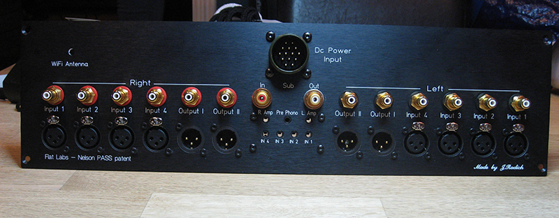
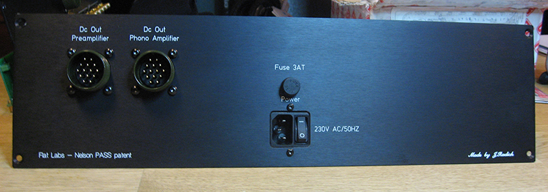
Can anyone help me with a CNC file for the front plate of the preamp? This is the last thing I have left to complete to finish it and it would be of theremendous help if someone can share or even sell his file... thanks in advance
This is how mine is going to be like...
In da works..


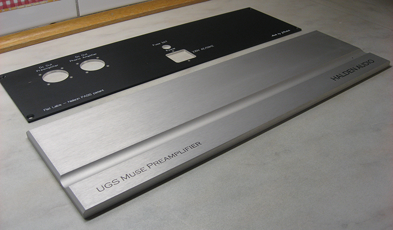
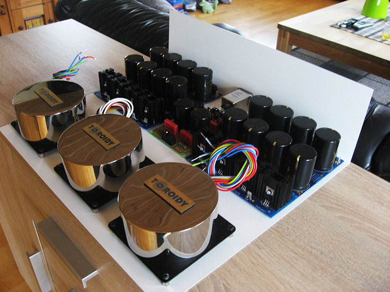
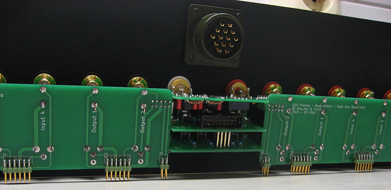
Just faceplates, nothing mounted in the cabinets yet, but all cards are ready soldered 🙂
Kind Regards
Johnny
In da works..
Just faceplates, nothing mounted in the cabinets yet, but all cards are ready soldered 🙂
Kind Regards
Johnny
Last edited:
- Home
- Amplifiers
- Pass Labs
- UGS-muse preamp GB