Hi,
sorry but I will complaining now:100k is almost nothing. There will be problem with the fast turn of of the output stage. I think that something 1-5k would be OK.
Sajti
sorry but I will complaining now:100k is almost nothing. There will be problem with the fast turn of of the output stage. I think that something 1-5k would be OK.
Sajti
sorry but I will complaining now:100k is almost nothing. There will be problem with the fast turn of of the output stage. I think that something 1-5k would be OK.
Right again. I didn't give it much thought when I added it.
While seeking a good operating point, I had to give the vas a little more bias current, so the spreader would be able to turn on all this stuff. I used 4k7 there on the pre-driver collectors, and those take away so much base current from the drivers, the O.Ds would no longer turn on and bias.
Dropping values on the pre-drivers' emitter res helps with that, and the gain is 10 with 470/4k7.
With more current going through those collector res than driving the drivers, this may not be so good and it's probably better to increase a bit the values of those collector res.
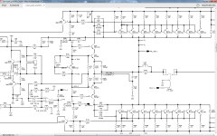
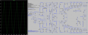
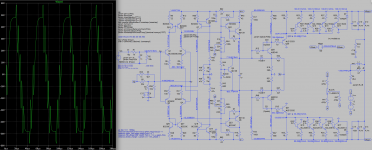
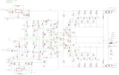
One thing remains, the oscillations.
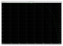
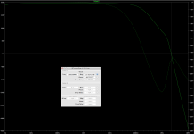
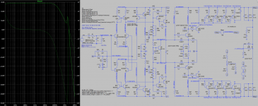
Although there is a small hint only left of the gain spike near 2mhz, the freq plot looks pretty good and a phase margin reads plenty, but nonetheless oscillations remain. For now. But I think this can be tamed.
Attachments
I don't get it.
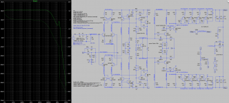
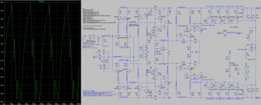
Only with the pre-drivers C-B caps can we get the good looking freq plot with none or only a hint of gain spike and earn some good phase margin, and yet, as long as those caps are there, we get lots of oscillations and nothing else can stop them.
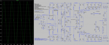
With those caps removed, the ones on the emitters allow to stop most of the oscillations, although not quite all. And the gain spike is back, but the output signal is looking more like a sine wave. And that's obviously when we get the best thd as well, since the oscillations are minimal.
Those left over oscillations look like only at crossover. But I have not found a way to get rid of those.
The global feedback comp cap seems optimal at 4p7 in any case.
Miller at 22-47p works most of the time, anything else lets more oscillations in.
I'm sure a comp guru could solve this and get it done right.
I'm going to try out something else, again...
Only with the pre-drivers C-B caps can we get the good looking freq plot with none or only a hint of gain spike and earn some good phase margin, and yet, as long as those caps are there, we get lots of oscillations and nothing else can stop them.
With those caps removed, the ones on the emitters allow to stop most of the oscillations, although not quite all. And the gain spike is back, but the output signal is looking more like a sine wave. And that's obviously when we get the best thd as well, since the oscillations are minimal.
Those left over oscillations look like only at crossover. But I have not found a way to get rid of those.
The global feedback comp cap seems optimal at 4p7 in any case.
Miller at 22-47p works most of the time, anything else lets more oscillations in.
I'm sure a comp guru could solve this and get it done right.
I'm going to try out something else, again...
Attachments
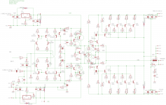
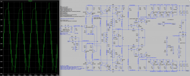
This is the way, how Crest Audio do it. This is not groounded collector version, however the output stage is common emitter too.
Yes, they do have good amps and interesting methods.
That cascoded pre-driver stage, and the local feedback scheme looks interesting.
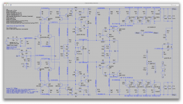
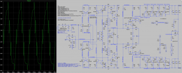
Tried various comp themes and this is the best so far that I could get.
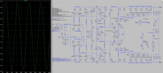
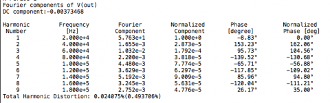
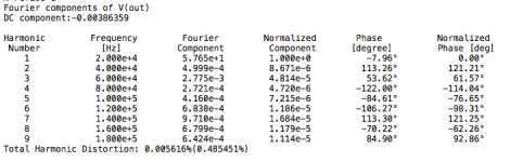
Considering that the gain spike is very present and well above unity gain, with that serious phase reversal, we have an amazingly low thd despite those hints of oscillation at crossover.
We can't keep the caps on the pre-drivers' C-B, although they do clean up the freq plots and allows a good phase margin, they also bring along serious oscillations, with any value.
I haven't been able to fully stop all hints of oscillation. But the best stability is only achieved when no caps are on the pre-drivers' C-B and when we have that nasty gain spike. Cleaning it up only causes issues. It's totally the opposite expected.
I tried a comp scheme picking up the output for feeding back to the comp caps at the pre-drivers emitters, instead of having them go to ground, but that didn't help.
This isn't very far from tamed, but a serious look is needed, and more than I can do myself.
Attachments
Good progress!
I am concerned about the oscillations that seem to do with crossover. I think it's worth bringing back the resistive divider on the input driver base to ground. My thinking is that this looks open loop at crossover and we should try to ensure it stays under control there. We had problems there and took it out, but I'm still thinking it is good concept, wrong part value so I put in a proxy value, slightly higher, but adjust as needed. What say you?
In another area, I'd like to convert the CFP VAS to EF VAS. The strange behavior in the output may be happening here. Try the EF to see.
So, two proposed changes. Maybe helpful. Adjust as needed. Merry simulations!
Attachments
Last edited:
I am concerned about the oscillations that seem to do with crossover. I think it's worth bringing back the resistive divider on the input driver base to ground. My thinking is that this looks open loop at crossover and we should try to ensure it stays under control there. We had problems there and took it out, but I'm still thinking it is good concept, wrong part value so I put in a proxy value, slightly higher, but adjust as needed. What say you?
Maybe. I'll try this next.
But in the mean time, I have a few results that may (or may not) provide you with a little insight about the origin and nature of the big oscillations.
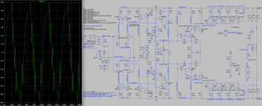
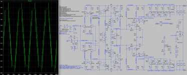
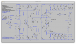
I wanted to try out something. Increasing a little bit further the ltp tail current, in turn leave the slight increase in vas bias as well and see what happens with no compensation at all on the power half...
Well, it kept oscillating of course, but I wanted to try what happened when upping the cap value on the pre-drivers' C-B and avoid using the ones on the emitters altogether, because although they do almost stop oscillations, they also are the ones bringing back that gain spike.
So I dared pushing the value well beyond reasonable on the comp caps on the C-B pre-drivers.
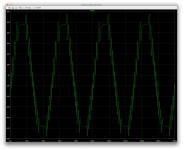
Although the results are never good, at any value, I think maybe, that seeing what the sine wave looks like at each value might tell a bit about the story there.
So here are some shots of that. Starting with 47p all the way to 2n (even 6n).
And by the way, at the same time I also changed the output stage gain to almost 8.4 because I also changed the collector and emitter res for the pre-drivers, trying to have more drive current going to the the drivers than to the collector emitters.
In another area, I'd like to convert the CFP VAS to EF VAS. The strange behavior in the output may be happening here. Try the EF to see.
In the output stage, can we get rid of the predriver? I did. The VAS is strong, no need for the predriver.
So, three proposed changes. Maybe helpful. Adjust as needed. Merry simulations!
So this means incremental changes and look at what happens with each change then.
So I suppose starting with the vas first and then get rid of the pre-driver next.
Attachments
-
 Screen Shot 2016-11-29 at 4.39.00 PM.png536.7 KB · Views: 63
 -
 Screen Shot 2016-11-29 at 4.38.36 PM.png545.5 KB · Views: 61
 -
 Screen Shot 2016-11-29 at 4.38.05 PM.png553.5 KB · Views: 60
 -
 Screen Shot 2016-11-29 at 4.37.32 PM.png563.5 KB · Views: 67
 -
 Screen Shot 2016-11-29 at 4.36.59 PM.png573.3 KB · Views: 54
 -
 Screen Shot 2016-11-29 at 4.36.29 PM.png591.8 KB · Views: 55
 -
 Screen Shot 2016-11-29 at 4.35.58 PM.png603.6 KB · Views: 67
 -
 Screen Shot 2016-11-29 at 4.35.19 PM.png611.5 KB · Views: 80
I seem to have a blind side for positive feedback. I think the feedback to the predriver emitter is positive. Remove it.
I seem to have a blind side for positive feedback. I think the feedback to the predriver emitter is positive. Remove it.
I've been working on slightly earlier versions, and adding your latest changes, but a bit hard to keep up ;-)
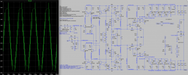
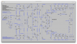
The bias doesn't work, as the vas bias current dropped a lot. I haven't tried yet to alter any values to correct things and didn't try centering. There is no point in trying to center if there is no bias flowing in the O.Ds.
I think a current snapshot of where I am now should help you sync me up, and see better what your latest change are doing.
Those 2 680k res feeding back to in+ definitely help center things, and the vas is more naturally centered without trying to force things. The output stages aren't centered, but nothing much is flowing there yet, so too early to tell.
Attachments
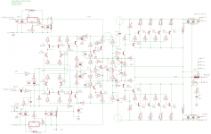
So, keep the 2 680k for the front end centering and get the bias spreader working so we can work on the output stage again.
From a previous post, it looks like the Vbias total should be about 1.56v. Vbias should be that, approximately, set the pot accordingly. I was aiming lower, forgetting we upped the predriver emitter resistors. We should have that voltage at the divider if we use about 330 ohms (not 249) plus 500 ohms from the pot per leg of the divider. (That is computed ignoring input current to the predriver, so it's still slightly low.) It would be easier if I could just plug numbers in the model, so in lieu of that I gave you two 1k pots to tweak. Start at 830 ohm and go up. Anyway, put the values that turn on the predrivers and center the output, separated from the input side. That should give a static DC solution and we can work on stability. I still think the NFB is PFB at those predriver emitters.
From a previous post, it looks like the Vbias total should be about 1.56v. Vbias should be that, approximately, set the pot accordingly. I was aiming lower, forgetting we upped the predriver emitter resistors. We should have that voltage at the divider if we use about 330 ohms (not 249) plus 500 ohms from the pot per leg of the divider. (That is computed ignoring input current to the predriver, so it's still slightly low.) It would be easier if I could just plug numbers in the model, so in lieu of that I gave you two 1k pots to tweak. Start at 830 ohm and go up. Anyway, put the values that turn on the predrivers and center the output, separated from the input side. That should give a static DC solution and we can work on stability. I still think the NFB is PFB at those predriver emitters.
Attachments

So, keep the 2 680k for the front end centering and get the bias spreader working so we can work on the output stage again.
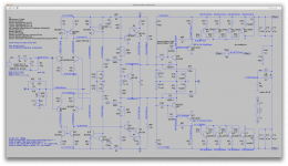
Ok, then once separated from the power half, the vas current can get to near 21mA by dropping its load res values to 18, from 42. Then it is fairly centered as it is when everything works normally, and there is enough oomph to bias the pre-drivers up.
From a previous post, it looks like the Vbias total should be about 1.56v. Vbias should be that, approximately, set the pot accordingly.
Maybe a tiny bit more, as I noticed how the lower side always needs a bit more to function. Due to models differences, but that's kind of closer to reality, as we're almost certainly not going to have npn and pnp better matched in the real world.
I was aiming lower, forgetting we upped the predriver emitter resistors. We should have that voltage at the divider if we use about 330 ohms (not 249) plus 500 ohms from the pot per leg of the divider. (That is computed ignoring input current to the predriver, so it's still slightly low.)
Actually if we keep the 15k res as is, we need a bit more there, with the feedback removed from the output, we end up with 600ohms to bring the stage in early conduction and a part of the way to biasing.
Then it centers nicely.
As shown the bias spreader doesn't spread as much as needed on the pre-drivers, but we should have plenty left to bring it up that way once the 2 halves are reunited.
It would be easier if I could just plug numbers in the model,
That can be done easily, if you want to grab the sim files and play with it on your end. It would surely go a lot faster.
Anyway, put the values that turn on the predrivers and center the output, separated from the input side. That should give a static DC solution and we can work on stability.
We probably could settle for a little less than the 600 at the pre-drivers, so it would be earlier in conduction and the bias spreader would handle the rest.
But this should work. We have a little more than 20mA in the O.Ds already, and nicely centered.
Attachments
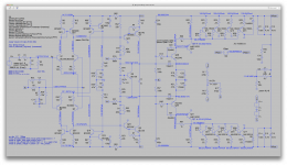
Correcting NFB to predrivers.
Ok, this isn't going to work as planned.
I tried tweaking but it's just not doing anything gently, and it's pushing the vas way out of balance.
It's likely I could center it, but with very dissymmetrical values on the pre-drivers.
It looked ok when split in half with simple values as it was, but once reunited, the vas gets disturbed and it's hard to balance.
Would you like to get the sim files and play around with this? It would be faster.
Attachments

Correcting NFB to predrivers.
This way isn't working out. Too much dissymmetry builds up when trying to center it. We can mostly center when it's split, mostly match the voltages on the spreader and pre-drivers, then once reunited it's not too bad, but the rails aren't centered and can't be brought back to center.
Something else is needed, it was working better before.
Attachments
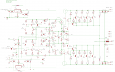
That just does not want to work. The attached just removes the 15k resistors to +-15v and the pots for bias adjust. Let's see if that at least can center.
I left the 100k resistors to the NFB point. They may be all we have to center the output by itself, which I am not comfortable with. But let's see how this settles down.
I left the 100k resistors to the NFB point. They may be all we have to center the output by itself, which I am not comfortable with. But let's see how this settles down.
Attachments

That just does not want to work. The attached just removes the 15k resistors to +-15v and the pots for bias adjust. Let's see if that at least can center.
Not by itself, and not without increasing the overly low bias in the vas. Taking the 42ohms down to 18 gets us back near 20mA in the vas, and then we're away from center with the high rail around 7V.
I left the 100k resistors to the NFB point. They may be all we have to center the output by itself, which I am not comfortable with. But let's see how this settles down.
Since it doesn't self center, I added the divider feeding the in- again, and got it biased and centered.
The bias spreader needs to spread nearly 2V, since we have already over 400mV on each of the pre-driver's emitter res.
Fairly centered, but not without forcing a little on the in- input.
Attachments
- Status
- Not open for further replies.
- Home
- Amplifiers
- Solid State
- grounded collector amp