Oh all right then...
"I cant get MJE243/253, can i use..."
I've used BD139/140 and MJE15032/3 with this circuit as well. The usual devices used as driver transistors in power amplifiers should work.
"BC847/857 are surface mount, can i use..."
I've used BC546/556 during prototyping. Any good small signal transistor should work.
"I cant get LT1115, can i use..."
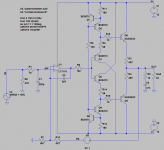
I only used that in the simulator. I used OPA2134 in my actual build. Any opamp should work but a FET input one means no appreciable offset voltage. C3 wasn't needed with the OPA2134.
If you wanna use a bipolar opamp you'll probably need a capacitor after R7.
My build also has a 3u3 Wima MKS2 input coupling capacitor "just in case".
"How do I alter the bias current?"
Adjust either R11/R12 or R2/R14. As shown should give about 40mA of bias, which will run most 32 ohm headphones in Class A.
"What about....."
This is DIY Audio... build it on breadboard and experiment 😉
"I cant get MJE243/253, can i use..."
I've used BD139/140 and MJE15032/3 with this circuit as well. The usual devices used as driver transistors in power amplifiers should work.
"BC847/857 are surface mount, can i use..."
I've used BC546/556 during prototyping. Any good small signal transistor should work.
"I cant get LT1115, can i use..."
I only used that in the simulator. I used OPA2134 in my actual build. Any opamp should work but a FET input one means no appreciable offset voltage. C3 wasn't needed with the OPA2134.
If you wanna use a bipolar opamp you'll probably need a capacitor after R7.
My build also has a 3u3 Wima MKS2 input coupling capacitor "just in case".
"How do I alter the bias current?"
Adjust either R11/R12 or R2/R14. As shown should give about 40mA of bias, which will run most 32 ohm headphones in Class A.
"What about....."
This is DIY Audio... build it on breadboard and experiment 😉
Attachments
Last edited:
In addition, you can connect the collectors of Q1 and Q2 to the emitters of Q5 and Q6 respectively, which lowers Q1/Q2's dissipation and improves THD a bit too according to LTSPICE.
I couldn't actually hear any difference, so I used this arrangement simply because it lowered the heat dissipated in Q1/Q2.
I couldn't actually hear any difference, so I used this arrangement simply because it lowered the heat dissipated in Q1/Q2.
Oh all right then...
"I cant get MJE243/253, can i use..."
I've used BD139/140 and MJE15032/3 with this circuit as well. The usual devices used as driver transistors in power amplifiers should work.
"BC847/857 are surface mount, can i use..."
I've used BC546/556 during prototyping. Any good small signal transistor should work.
"I cant get LT1115, can i use..."
I only used that in the simulator. I used OPA2134 in my actual build. Any opamp should work but a FET input one means no appreciable offset voltage. C3 wasn't needed with the OPA2134.
If you wanna use a bipolar opamp you'll probably need a capacitor after R7.
My build also has a 3u3 Wima MKS2 input coupling capacitor "just in case".
"How do I alter the bias current?"
Adjust either R11/R12 or R2/R14. As shown should give about 40mA of bias, which will run most 32 ohm headphones in Class A.
"What about....."
This is DIY Audio... build it on breadboard and experiment 😉
It should stabilize (thermally). Those extra two transistors +diodes (near Q5-6)
will absolutely lock the class A dissipation of Q5-6 and make the output
short circuit proof.
Me and J wilhelm have the complete PCB's - this works (well).
OS
Yep figured you'd have played with this topology ostripper 😉
I'm happy with it. Used the breadboarded version for a while until a wire came loose and cost me my Beyer DT231's in the process ! Now using a PCB version with a pair of Sennheiser HD497's
I'm happy with it. Used the breadboarded version for a while until a wire came loose and cost me my Beyer DT231's in the process ! Now using a PCB version with a pair of Sennheiser HD497's
Yep figured you'd have played with this topology ostripper 😉
I'm happy with it. Used the breadboarded version for a while until a wire came loose and cost me my Beyer DT231's in the process ! Now using a PCB version with a pair of Sennheiser HD497's
Me and W actually went one step further and have two Jung feedback
precision regulators supplying the +/- 15V to the diamond/output/IC (>-120psrr).
OS
Hi ostripper,
I've built many of these over the years and have never been disappointed with the results.
-Chris
Looks like I really, really have to talk to Jeff about this. There was too much going on for me to remember everything. So what performance gains did you see using the regulators? I typically use CCS circuits for the same positions that you do. These darned things are so quiet anyway ...Me and J wilhelm have the complete PCB's - this works (well).
I've built many of these over the years and have never been disappointed with the results.
-Chris
Sure, but in fact I do not need simulation to be able to broadly predict the effects of individual temperature changes: if the T° of one or both drivers increases, it will decrease the quiescent current, and vice-versa for the OP's.You could explicitly set the junction temperatures in simulation and find out whether an increase in driver temperature results in an increase or decrease in output stage bias current (in simulation). You could try this for various different choices of device types (.MODELs) from different semiconductor vendors, to reduce the possibility of incorrect conclusions resulting from bad model parameters. For example I find wide variability in the simulation models of BD139 from different semi companies.
The real difficulty is to understand the complete system with its interaction of self- and induced-heatings, the thermal resistance of the various devices and their mounting, and the thermal resistance and inertia of the heatsink.
The whole think seems to be stable without emitter resistances, but it goes somewhat against common sense, and I am reluctant to draw general conclusions from two examples
Sure, but in fact I do not need simulation to be able to broadly predict the effects of individual temperature changes: if the T° of one or both drivers increases, it will decrease the quiescent current, and vice-versa for the OP's.
The real difficulty is to understand the complete system with its interaction of self- and induced-heatings, the thermal resistance of the various devices and their mounting, and the thermal resistance and inertia of the heatsink.
The whole think seems to be stable without emitter resistances, but it goes somewhat against common sense, and I am reluctant to draw general conclusions from two examples
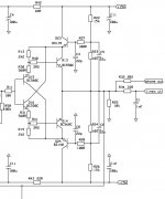
This one is used in my GainWire preamp with no emitter resistance and is thermally stable, just thermally connected Q15-Q13 and Q16-Q15.
Attachments
Me and W actually went one step further and have two Jung feedback
precision regulators supplying the +/- 15V to the diamond/output/IC (>-120psrr).
OS
Overkill perhaps. I just used 7812/7912 as I had them to hand 🙂
One more confirmation then.This one is used in my GainWire preamp with no emitter resistance and is thermally stable, just thermally connected Q15-Q13 and Q16-Q15.
Good to know, it strengthens the case.
Member
Joined 2009
Paid Member
why is this diamond buffer stable without emitter resistors whereas the traditional EF with bias spreader for thermal feedback is not ???
Hi Gareth,
Because the Vbe junctions cancel each other very nicely. That's why they are thermally coupled the way they were described above be dadod.
-Chris
Because the Vbe junctions cancel each other very nicely. That's why they are thermally coupled the way they were described above be dadod.
-Chris
I haven't found satisfactory theoretical explanations so far: I can just see that in reality, it seems to work.why is this diamond buffer stable without emitter resistors whereas the traditional EF with bias spreader for thermal feedback is not ???
There is certainly more than just compensation at work here, because as we all know, with discretes, just a bias spreader and no emitter resistors is a very fast path towards molten silicon.
The very high quiescent dissipation in the drivers seems to be a (big) part of the answer as to why, but I do not see exactly in which way.
Anyway, the provisional prototype I experimented was so successful that I am currently casting it into something permanent, with a case, supplies, controls and connectors.
Maybe I am too optimistic.... future will tell
Elvee, I need a buffer, but inverting one with or without global NFB. Important is to have low distortion and to be quite simple. I simulated one in mine GainWire mk3 thread, but I am not very satisfied with it, to complicate. Do you have any good idea?
Damir
Damir
Member
Joined 2009
Paid Member
The very high quiescent dissipation in the drivers seems to be a (big) part of the answer as to why, but I do not see exactly in which way.
It could be very nice to avoid emitter resistors and I would love to know what criteria are required to achieve it.
Is there something here (Bob Pease) ?
"If you need to know the tempco of VBE, it normally changes - 200 uV/degree C every time the current is reduced by a factor of 10."
What's All This VBE Stuff, Anyhow? nsc03943 - Datasheet Archive
perhaps consider an input transformerI need a buffer, but inverting one
Last edited:
Member
Joined 2009
Paid Member
Regardless, we can always design a Vbe multiplier / bias spreader to have enough temperature compensation. So why do we still need emitter resistors ?
Is it that the junction temperature of the power device still changes too rapidly for the thermal feedback loop to operate in time ? I don't think this is it.
AND
did you / can you try placing the drivers not on the heatsink but on top of the power devices so that they sense the temperature of the power device directly ? - they would run hotter of course but are essentially still being cooled by the heatsink via a 'hot' washer !
Last edited:
Hi Gareth,
-Chris
That is what happens when the thermal feedback includes the main heatsink. The response does lag the action by a significant amount. This is why the thermaltrack devices are such a welcome advance. If you use those diodes as temperature sensors you will be closer to the thermal event. Why not start there?Is it that the junction temperature of the power device still changes too rapidly for the thermal feedback loop to operate in time ?
-Chris
The high driver current is the key, as they are pre-empting any temperature rise in the output stage. I suspect that if you did the same in a conventional bias spreader and made it into a significant heat source, it would work the same.
I think that this technique would fall down if the output transistors power dissipation was considerably higher than the bias spreader though, but happy to be proved wrong.
Brian
I think that this technique would fall down if the output transistors power dissipation was considerably higher than the bias spreader though, but happy to be proved wrong.
Brian
- Status
- Not open for further replies.
- Home
- Amplifiers
- Solid State
- A diamond paradox?