Hi.
I connect a 4ohm Resistors to output. and 50Hz signal to Input.
The voltage across 4Ohm resistor was 31.2V, according to this the power of amp must be 243W .
is this an incorrect power calculating?
thanks
I connect a 4ohm Resistors to output. and 50Hz signal to Input.
The voltage across 4Ohm resistor was 31.2V, according to this the power of amp must be 243W .
is this an incorrect power calculating?
thanks
Hi.
I connect a 4ohm Resistors to output. and 50Hz signal to Input.
The voltage across 4Ohm resistor was 31.2V, according to this the power of amp must be 243W .
is this an incorrect power calculating?
thanks
Yes but output signal must be without clip.
Regards
Hi.
thanks for your reply.
Actually Apex Ax-14 has one pair of 5200 and 1943.
How is it able to produces 243W on 4Ohm load?
It's amazing.
thanks for your reply.
Actually Apex Ax-14 has one pair of 5200 and 1943.
How is it able to produces 243W on 4Ohm load?
It's amazing.
Amplifier output must be measured before clipping levels.Hi.
I connect a 4ohm Resistors to output. and 50Hz signal to Input.
The voltage across 4Ohm resistor was 31.2V, according to this the power of amp must be 243W .
is this an incorrect power calculating?
thanks
In order to measure a non sinusoidal wave (such is a clipped signal) you need a true RMS voltmeter or a scope meter.
the stress of driving a reactive speaker load is VERY much MORE than that when driving a resistive load.Hi.
thanks for your reply.
Actually Apex Ax-14 has one pair of 5200 and 1943.
How is it able to produces 243W on 4Ohm load?
It's amazing.
I expect ALL competent amplifiers to drive a resistive load that is half of the nominal speaker load rating.
i.e. you have a 100W into 8ohms amplifier and it must be capable of driving a 4r0 dummy test load. If it can't then it's not an 8ohms amplifier.
I expect my amplifiers to drive a dummy resistive load of less than 1/3rd of the rated speaker impedance. This is tested to ensure that the amplifier can supply transient peak currents that are three times what the rated load would pass if it were purely resistive.
i.e. that 100W into 8ohms amplifier must be able to pass ~15Apk (instead of 5Apk) for a couple of seconds into a 2r6 load without the supply collapsing, or the amplifier blowing up, or the current limiters triggering.
That does not solve the problemAmplifier output must be measured before clipping levels.
In order to measure a non sinusoidal wave (such is a clipped signal) you need a true RMS voltmeter or a scope meter.
Take a square wave and drive an amplifier to just about it's maximum output voltage. use an rms meter to measure that voltage.
A 100W amplifier will measure 200W driving an 8r0 load.
Reduce the test voltage slightly to account for the more sagged supply rails and attach a 4r0 test load and the rms meter will measure a voltage that calculates out at getting near 400W into 4r0
An averaging voltmeter will similarly read these nonsense voltages. There is no point in reading the VOLTAGE of a severely clipped output signal. Much more relevant is how the amplifier comes out of clipping and that can be examined without a voltmeter.
A severely clipped sinewave is beginning to approach a squarewave. The rms meter will measure these nonsense voltages and give nonsense output powers.
He needs an oscilloscope and a distortion meter. He takes the test voltage up gradually to just short of the clipping level and measures the distortion to be equal to 0.1%. make a fine adjustment to the test signal to meet that 0.1% THD figure and measure the output sine wave into the accurate test load. Calculate the output power.
It is no good having an 8r0 dummy load that rises to 9r35 when hot. That will not give the power into an 8ohms load.
Last edited:
Hello,
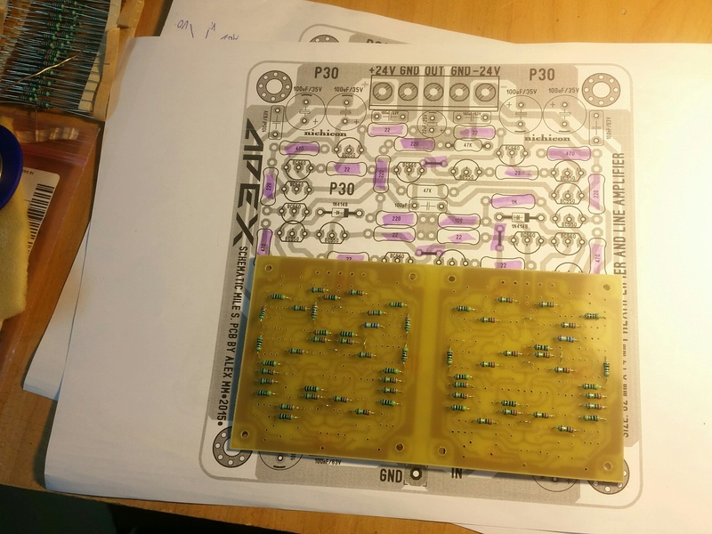
work in progress ... preamp apex P30 ...
Thanks to Alex mm and still4given, for help me ..
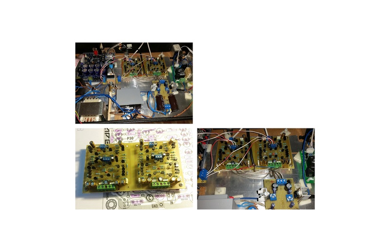
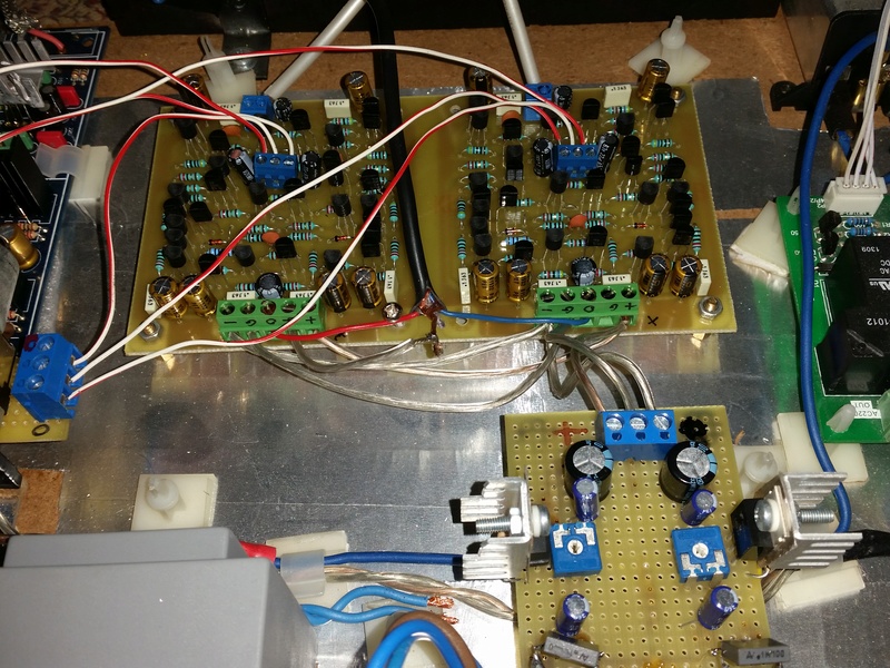
Hi guys,
..preamp P30, finished, I started to test it ... the sound is very analogue is hot remember me 80 years ... really great preamp ... although not yet made a PSU class A to put into it. Excellent combined with my amplifier APEX HV23. Ask you, if there are voltage values to be checked on it or else ... to see if both channels sound the same ...
Thank you
If any of you guys has a pair of pcb s for the preamp apex P30 I would love to buy them from you.
10k across the output inductor.
Is that a typo?
Yes it is typo and now is corrected, thank you.
Regards
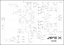
I wish I could follow the topology.
Would it be possible to give a "layman's" explanation of how it works?
Would it be possible to give a "layman's" explanation of how it works?
I wish I could follow the topology.
Would it be possible to give a "layman's" explanation of how it works?
Amplifier output is grounded instead PSU center tap which floating.
Amplifier output is grounded instead PSU center tap which floating.
I found this here on diyaudio, hope it helps to understand this circuit: http://www.diyaudio.com/forums/solid-state/2696-what.html
I'd like to try this design.
A side note: to make a stereo amp with this design, you'd need 2 separate secondary windings, 1 for each amplifier.
If you are right then you need two isolated channels. That requires 4 secondary windings, or two centre tapped windings.I found this here on diyaudio, hope it helps to understand this circuit: http://www.diyaudio.com/forums/solid-state/2696-what.html
I'd like to try this design.
A side note: to make a stereo amp with this design, you'd need 2 separate secondary windings, 1 for each amplifier.
Thanks for the link.
If it is truly floating, could one not force a virtual floating ground and actually use a single rail supply? That would be useful.
- Home
- Amplifiers
- Solid State
- 100W Ultimate Fidelity Amplifier