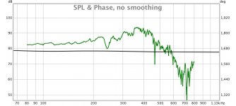
Had just enough time this afternoon to get one woofer on and to do a FR test (indoors) before dinner with friends.
2x 38mm ports gave the following result. Note that this was with the rear of the woofer running 'freespace'- not enclosed in a airtight box. Mic was close to the horn mouth so hopefully not giving too much of a misleading result.
As fluid suggested, I can see port chuff being an issue with the ports sized this way. Tomorrow I will elongate them to the suggested 20% of SD- albeit in a pill shaped port.
Attachments
Before I made the holes larger, I would "frustrumize", them as tapering the sides of the holes and/or thinning out the horn wall in their vicinity will reduce chuffing. I would also want to hear chuffing or measure inordinately high distortion at high volume, not attributable to high excursion, before I concluded the holes needed to be twice as large. The hole size needed also depends on how loud you intend to play. Use in home at reduced SPL compared to a public venue, allows significantly smaller holes.
I see your woofer is playing fairly high, allowing considerable overlap with your mids. A first order XO would be a nice simplification.
I see your woofer is playing fairly high, allowing considerable overlap with your mids. A first order XO would be a nice simplification.
Before I made the holes larger, I would "frustrumize", them as tapering the sides of the holes and/or thinning out the horn wall in their vicinity will reduce chuffing. I would also want to hear chuffing or measure inordinately high distortion at high volume, not attributable to high excursion, before I concluded the holes needed to be twice as large. The hole size needed also depends on how loud you intend to play. Use in home at reduced SPL compared to a public venue, allows significantly smaller holes.
I see your woofer is playing fairly high, allowing considerable overlap with your mids. A first order XO would be a nice simplification.
All good points, if you have a roundover bit for your router you could put a small roundover on the inside and outside of the ports which will allow the smaller ports to work at a higher velocity before chuffing occurs.
As long as the ports are far enough away from the throat making them a bit bigger shouldn't really have a down side though.
Have you tested the response of the CD on the bare horn and then with the ports cut to see what effect they had?
Also looks like your thread title got moderated😉
The port sizes on those 10inchers looks like a tough thing to crack.
Something to consider? - we all like to port the woofers into the horn, in good agreement with Synergy horn principles, but look at the wavelength of your woofer's frequencies. The 300Hz crossover frequency means the center of the woofer outputs can be as far as 11 inches out from the tweeter throat and it will still look like a point source. The horn will do not a lot if anything for low frequencies, and the overall sensitivity will depend on what the woofers do much lower than that. So maybe put the woofers on the front baffle (not in the horn), but mounted inside the baffle and partially behind the horn walls, and firing through a wide slot so the center of the woofer ports are within the 11 inches.
I did something like that on the SmallSyns, though with much smaller horns and woofers, and it worked out really well. You can even do some tricks with spacing of the slots to extend directivity about another half octave down (from array effects, rather than horn pattern control). It depends, though on how much of the woofer you can put behind horn walls and how big the horns are. If the horn is big enough that it is working to low frequencies, then you probably do need to get the woofer firing into it's insides.
Bill,1)Something to consider? - we all like to port the woofers into the horn, in good agreement with Synergy horn principles, but look at the wavelength of your woofer's frequencies.
2) The 300Hz crossover frequency means the center of the woofer outputs can be as far as 11 inches out from the tweeter throat and it will still look like a point source. The horn will do not a lot if anything for low frequencies, and the overall sensitivity will depend on what the woofers do much lower than that. So maybe put the woofers on the front baffle (not in the horn), but mounted inside the baffle and partially behind the horn walls, and firing through a wide slot so the center of the woofer ports are within the 11 inches.
3)If the horn is big enough that it is working to low frequencies, then you probably do need to get the woofer firing into it's insides.
1) I don't know that "you all" will get total agreement with Tom Danley regarding what you wrote, but have not consulted with him as to what his opinion would be regarding your statement, so will go with y'alls ritin' ;^).
2) Or front mounted on a large panel, so the natural delay of LF transducers is compensated for by their shorter path length to the listening position and has boundary reinforcement from a "largish" front panel that can extend from the desired multiple entry horn desired height all the way to the ground plane, if it has the requisite aesthetic acceptance level.
3)"Need", or desire- oh the dilemmas we must consider when we DIY.
Thanks again for all your contributions that have alleviated myass being impaled on the "horns of a dilemma" during the first iteration of the SynTripP installment plan.
Cheers,
Art
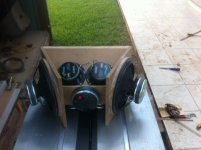
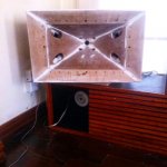
Just for some clarity on my current driver/horn arrangement.
The 10" woofers are mounted on a 12mm doughnut. Those are mounted to a baffle that attaches to the side of the horn. Part of the baffle is removed to allow the output of the 10" to enter a small chamber that runs along the side of the horn wall before porting out into the horn mouth through the pill shaped ports (which have now been extended.
Working on a simple removable rear enclosure so I have something a bit more complete to start doing some more comprehensive measurements.
Mark
Attachments
That room between the ports of the woofer isn't causing any trouble? It looks like a bandpassed bandpass... Making the path from the woofer to the horn that much longer too.
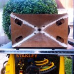
Ok so this afternoon I spent quite a while mucking around making a removable 2nd flare for the horn. Things get tricky very quickly as soon as you are working with compound angles! I have a solution that is not very neat but quite usable for the meantime.
Other than that the cabinet is all boxed up (i am still chasing a few small leaks that are probably impacting Woofer performance at higher SPL)
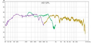
It is dark and full of mosquitos outside so I'm having to do a few basic FR tests indoors to get my DIY audio fix for the evening. Below is a chart of the driver raw responses (no xo, no PEQ). On the DSP I have the 10" faital woofers -10db, the mids at 0db and the PRV CD at -10db.
So I guess I need to start thinking about xo's and PEQs. I have all the functionality of a mini dsp4x10 at my disposal but not a lot of knowledge about crossover types, slopes, etc. I've read about other peoples positive impressions of using a Harsch XO arrangement but am none the wiser as to how to implement one! Other terms that get bandied around like, phase coherent leave me scratching my noggin...
Anyone know of a good guide to XO design with the Mini dsp/REW combination? I'll try to attach the MDAT files so people can play along at home (but I am not averse to learning some new skills myself).
Note: I've had to attach a limited passband measurement of the CD to keep the file small but the vital XO section is included. I think the response on the CD is suffering from a slight mis-alignment of the exit to the beginning of the waveguide. I need to file off a lip that I suspect is contributing to its dippy response at the moment.
Mark
Other than that the cabinet is all boxed up (i am still chasing a few small leaks that are probably impacting Woofer performance at higher SPL)
It is dark and full of mosquitos outside so I'm having to do a few basic FR tests indoors to get my DIY audio fix for the evening. Below is a chart of the driver raw responses (no xo, no PEQ). On the DSP I have the 10" faital woofers -10db, the mids at 0db and the PRV CD at -10db.
So I guess I need to start thinking about xo's and PEQs. I have all the functionality of a mini dsp4x10 at my disposal but not a lot of knowledge about crossover types, slopes, etc. I've read about other peoples positive impressions of using a Harsch XO arrangement but am none the wiser as to how to implement one! Other terms that get bandied around like, phase coherent leave me scratching my noggin...
Anyone know of a good guide to XO design with the Mini dsp/REW combination? I'll try to attach the MDAT files so people can play along at home (but I am not averse to learning some new skills myself).
Note: I've had to attach a limited passband measurement of the CD to keep the file small but the vital XO section is included. I think the response on the CD is suffering from a slight mis-alignment of the exit to the beginning of the waveguide. I need to file off a lip that I suspect is contributing to its dippy response at the moment.
Mark
Attachments
So I guess I need to start thinking about xo's and PEQs. I have all the functionality of a mini dsp4x10 at my disposal but not a lot of knowledge about crossover types, slopes, etc. I've read about other peoples positive impressions of using a Harsch XO arrangement but am none the wiser as to how to implement one! Other terms that get bandied around like, phase coherent leave me scratching my noggin...
Anyone know of a good guide to XO design with the Mini dsp/REW combination? I'll try to attach the MDAT files so people can play along at home (but I am not averse to learning some new skills myself).
There are many choices for crossovers but the aim of any is to get the best blend of frequency and phase response through the crossover region.
Your mid and CD don't have much overlap so you will probably need to use the acoustic slopes you already have to some degree and will probably be looking at EQ and maybe first order electrical to get the desired response rather than a textbook filter.
The woofer and mid has more overlap so you can use a more standard filter for the woofer crossover if you want.
One of the first things is to see whether the drivers are time aligned well enough from the physical offsets or if you will need to use delay to bring them into alignment this is a good first step as it will make the next stages easier.
A Harsch crossover uses particular electrical slopes combined with a delay to produce a crossover that has some frequency response ripple but a fairly flat phase through the crossover region. If you think that a flat phase is important you can give this a try. It is also possible to use FIR filters to completely change the phase afterwards so if you are prepared to go down that road then the Harsch is not really necessary.
There is a thread on it here
http://www.diyaudio.com/forums/multi-way/277691-s-harsch-xo.html
nc535 has posted a lot of information and graphs on the later pages of his thread for a synergy style horn. The idea of using a fixed target slope to EQ to was shown and that can be a useful way of making sure you are actually getting the slope you intended.
http://www.diyaudio.com/forums/multi-way/291160-my-synergy-corner-horn-bass-bins.html
I'm sure you'll get more information from others shortly
Anyone know of a good guide to XO design with the Mini dsp/REW combination?
Mark
I suggest you download Charlie Laub's Active Crossover Designer (ACD) which allows you to target MiniDSP. You can find it by googling. It includes a tutorial/example. However, I suggest you use the impulse response method to achieve time alignment instead of what is shown in the example. Time alignment is essential to creating a point sourse and I found the IR method to be more precise than the 3 measurement method.
That is: you set REW up with a reference loopback connection on ch2, take IRs of each driver separately, then set DSP delays so that the first IR peak of both drivers occur at the same time. Then implement the IR filters and repeat the time alignment step to compensate for any differential filter delay. Driver polarity is correct when both IRs initial peaks are in the same direction.
When doing your EQ and XO filters, you can import a filter target curve into ACD. In my thread, Wesayso showed how to generate target curves using RePhase and REW.
Some more thoughts for you, the band limited files won't be a great deal of use, you could turn them into frd and zma files which can be used in most of the crossover simulators and they are much smaller files.
One standard approach to active crossover design is to time align the drivers, equalize them to be flat to 2 octaves either side of the crossover point and then apply a textbook crossover, often a 4th order Linkwitz Riley. You can then undo the phase wrap from the filter with various methods if you think that is worthwhile.
This won't really work with any synergy as the acoustic bandpass limits the overlap. The idea of equalizing the drivers to as flat a response as you can get is not a bad idea to start with though as you have plenty of Parametric EQ in the minidsp and auto EQ with REW can get you in the ballpark simply.
Your woofer to mid could cross anywhere between 250 and 450 but 300Hz looks good as it will be easy to EQ out the bump at the bottom of the mid.
Crossing your CD as high as possible is a good idea to limit the distortion as the lower you cross it the harder it will have to work. There is already a reasonable acoustic cross between them at around 1200Hz, you could pick that as a crossover point and try to get a good match with low order slopes and some EQ.
Have a search through Bill waslo's threads here and on diysoundgroup as there are a lot of graphs and information on the crossover's he has used with synergy style speakers. Look through any of the threads on synergies where there are raw measurements and crossover measurements as they will give you some ideas on what other's have done.
Many crossover tutorials focus on 2 way dome tweeter / cone woofer systems and that approach is not well suited to your situation.
As you don't like simulation you can always rig the minidsp up and measure as you go to see what the effect is as you add different slopes or vary the EQ.
Other than the tweeter, that's a pretty decent result you have. I'd try to see if you can get the tweeter response a little cleaner (alignment to throat, if that's it), then just wing it with the miniDSP for the time being. Use some low-order Butterworth filters to trim the responses beyond their used bands and to limit low frequency power going to the tweeter, play with delays (you'll likely need to add some delay to the tweeter relative to the midrange, at least I always did) to help smooth the crossover regions. Just watch the responses as you go and adjust (if you can watch phase response, too, and can trim out time-of-flight delay from the measurement phase curves, watch to get that as least wild in the overall combined response as you can. As long as you protect the driver(s) from getting over-driven, trial and error can be surprisingly successful there. Because of the generally point source nature of a synergy horn, you don't have to worry too much about getting the phases to track between drivers as the on-axis response will be pretty close to the off-axis response, no lobes to worry about.
Please excuse the hijack, is there a thread somewhere that discusses the port location in the horn ie. the sides vs. the corners or round vs. oval? I see Bill's recent designs are pushing toward the corners.
I don't think you will find a thread that goes into it in any depth. The theory is that there is less sound pressure in the corners so holes there affect the pattern less than anywhere else. Oval holes in the corner get more of the hole area close to the corner and thus ostensibly do least damage to the pattern, and what damage there is likely occurs well off axis. People have gotten good results with round holes not in corners so its not clear how much it matters. If you listen on axis, you at least want the holes as far off axis as you can get them, but you probably don't need to strain for that last 1/8"
One thing I learned by time-wasting experience is that you absolutely DON'T want the ports to get too far away from each other -- quarter wave max from any other identical port would be a good guide, closer is better. I made some absolutely gorgeous oak wood-grain matched horns and went to the trouble to move the ports into the corners on the theory that it would hide them. The pretty horns' performance basically sucked. The main difference between those horns and the previous ones (which had worked out very nicely) was that the mid ports were pushed out into the corners and too far from the others, causing some odd lobing. Since then, I arrange so that the ports form a square (when viewed from directly on the horn's axis) even when the horn is rectangular rather than square, keeping them as close to the others as possible. That has worked out much better (though it's not like I've made dozens of these -- who knows, something else might have been causing issues instead that I just didn't catch?).
Possibly my most effective synergy-ish horns have used only one midrange driver (not 2 or 4) feeding a total of two ports (not 4), both below the tweeter. That keeps them closer to each other and minimizes the holes in the horn walls in general. It makes the structure less symmetric, but the overall performance seems more clean. Brains like the idea of symmetry, but I don't think there's any actual acoustic benefit, and maybe there's a disadvantage in fact.
Possibly my most effective synergy-ish horns have used only one midrange driver (not 2 or 4) feeding a total of two ports (not 4), both below the tweeter. That keeps them closer to each other and minimizes the holes in the horn walls in general. It makes the structure less symmetric, but the overall performance seems more clean. Brains like the idea of symmetry, but I don't think there's any actual acoustic benefit, and maybe there's a disadvantage in fact.
Last edited:
Ok so a small update from my end of things. So it seems as though my prototype box is performing well enough that I will replicate it for my stereo pair. In pulling it apart and working on some throat smoothing, puttying, sanding, and general tidy up I discovered that over time a fair amount of dust and fine sawdust had made its way into the CD. I removed the rear cover and there was a small pile of crud up against the diaphragm... so that may have been affecting my CD response in those last charts. I cleaned it out and then realised that I didn't note which way the diaphragm was installed so I may have the polarity switched now... Any idea or a simple way to check? I know the 9v battery trick with woofers but assume that would not be noticeable on a CD diaphragm.
I have sacrificed a Yoga mat to act as gasket for the rear hatch, and for the wave guide/box attachment which has sorted out the air leakage issues I was having previously. I also braced the rear box with some thin strips of 12mm Ply and have it stuffed fairly lightly with some polyfill. I've also made a removable 2nd flare (currently out of ply but I think I will make it out of some nice hardwood as a bit of a feature now that I have the dimensions figured out) I've seen some people go to the lengths of adding mass and dampening by using a bitumen/small rocks slurry, and by adding foam to the rear caskets of the woofer to stop reflections/resonances. Might look into that down the track if people think it is a worthwhile investment in time.
All in all I am very happy with the form of the box. It is very compact while still having 2 handles and space for a pole mount in the bottom which will make it versatile for me.
Next week I'll hopefully get some outdoor measurements to dial in the time alignment and start on the XO adjustments. As for now it is providing some nice sounding background music for a scheduled (and much required) day of spring cleaning...
Mark
Attachments
Do a test with REW with only the CD and look at the impulse. If it goes up first then you have the polarity correct if it goes down first then it is inverted. If it is backwards you could switch the leads over rather than refit it.
Nice job. You can no doubt appreciate how hard it is to get the clean joints that Bill had in his wood grain horn and how frustrating it must have been for it not to work. I would have found a CD that tolerated a low XO frequency and claimed that is what I wanted to do all along🙂
Before you add mass and damping to your horn flares you should brace them really well. Chances are the woofer frames brace the vertical flares fairly well already but two or three braces running front to back between the horizontal flares and the top and bottom of the box will really stiffen them. Perhaps to the point where you feel that you don't need damping. It worked that way for my 12mm thick BB horn flares. Knuckle testing was almost like rapping my granite kitchen counter tops.
I would be cautious about shooting spray foam inside the horn. Too much can blow things apart but, also, it might not have the desired effect. Back in the day I built a house using spray foam to seal pre-fabbed closed cell foam panels together and later, in another house, sprayed foam into previously un-insulated walls. Those walls turned out to be almost totally transparent to sound. My current residence has open cell foam in its walls which have good sound insulation.
Closed cell foam hardens into a rigid structure that transfers vibration from one wall to the opposite with little attenuation. Those spray cans you find in stores like Home Depot and Lowes are all closed cell foam. Open cell foam doesn't get completley rigid and thus provides some damping but it only has about half the R-factor of the closed cell foam. I would only use foam if I could get open cell foam, which is hard to find. My feeling is that with good bracing you don't need it.
Agree with nc535 on the horn walls -- that particular structure, particularly when braced with metal driver frames over most of its surface, is pretty darned inert already, at least was on mine. The walls of the box I used behind the woofers needed bracing, though, but that was pretty easily done with half inch plywood shelf braces. An often unmentioned benefit of horn gain is that the drivers won't shake their structure all that much, since less solid cone/dome movement is needed to move the air than with a direct radiator that has to shake itself hard so that the air around it can get shoved a little bit!
- Status
- Not open for further replies.
- Home
- Loudspeakers
- Multi-Way
- The **** Synergy: learning the art.