https://www.bksv.com/~/media/literature/Product Data/bp2212.ashx
Is the data sheet for a 1/2" Bruel & Kjaer capsule. It does wiggle a bit at the top end, but look at the divisions! 2.5 dB per line so the wiggle by carefully exploding the data sheet it =/- 1/2 dB!
I expect similar results for most quality measurement microphones.
Even better https://www.bksv.com/~/media/literature/Product Data/bp1844.ashx
Very impressive FR. No FR cal file even needed with that 4938 but so expensive (IMO).
Less so than you think, just like you can make a +- .1dB piston phone out of a $15.00 medical grade pressure transducer. The same one Jim Willams used for his barometer. You might need a piece of mailing tube, etc.
If not the spark cal, what do think would cause the EW mic cal deviations?
EW M30 is a free field mic. If spark cal directly provides the pressure FR (asking, not sure), could the EW pressure->FF compensation be the cause?
The Earthworks microphones can only get a frequency response calibration free field. I don't think there is a way to use an electrostatic calibrator on a Panasonic mike. A standard calibrator worked in the pressure range where the cavity is small enough to be pretty uniform inside.
A 4 dB absolute error seems exceptional and unlikely. I would first check the rest of the chain for some other error (diff singla shorted to ground etc.). The ECM mikes are not as stable as the metal diaphragm types but usually is only 1/2 dB or so. The MEMs mikes are the most predictable and stable but have a host of other limitations.
A 4 dB absolute error seems exceptional and unlikely. I would first check the rest of the chain for some other error (diff singla shorted to ground etc.). The ECM mikes are not as stable as the metal diaphragm types but usually is only 1/2 dB or so. The MEMs mikes are the most predictable and stable but have a host of other limitations.
If not the spark cal, what do think would cause the EW mic cal deviations?
EW M30 is a free field mic. If spark cal directly provides the pressure FR (asking, not sure), could the EW pressure->FF compensation be the cause?
I don't know but here's what I did. This was a period of hard core DIY so bear that in mind. I went to Home Depot and bought a piezo grill starter assuming it made an acceptable spark and made a gap from two needles at the end of two long dowels. I was careful to keep all reflections and the sound of pushing the starter button at least 5 or 6 ms away from the pressure wave of the spark. I turns out a spark is actually a doublet (no DC if you think about it), no problem simple integration yields an impulse. Well it turns out the initial heating of the air is a shock wave and now some serious maths must be invoked. Beyond 5 or 6kHz you need some Bessel functions, etc. to get a fit. Thankfully nuclear bombs also produce shock waves and a very smart Russian physicist provided the maths.
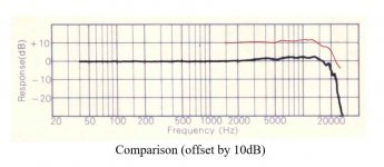
The picture tells it all. Back in the 70's Nakamichi sold some very nice microphones and the pinpoint omni even came with individual calibration produced on a standard B&K swept sine/isolation chamber setup. The chart that came with mine was so close to the one in the data sheet that I just scanned in the one on the data sheet and compared it to the corrected one that I measured. I though pretty darn close, certainly close enough that no speaker project that I was going to do would benefit from anything better.
Attachments
Last edited:
The MEMs mikes are the most predictable and stable but have a host of other limitations.
I use one of these as a DC to 3kHz "microphone" or actually to sample the pressure inside a small home brew piston chamber. The sensitivity is laser trimmed to the equivalent of .1dB and they are good enough for life support use. The most sensitive one is only about 15uV/PA so I use a G1000 in-amp. The small speaker driven chamber had a 350Hz resonance and high enough Q to measure sensitivity and THD up to ~150dB SPL. Ed made fun of me but the numbers looked very good and it was DIY so I was happy (and it cost $0 because the sensor was a board pull).
NPC-1210
I don't remember making fun of you for that. I generally have the highest regard for you. Although we do have trouble communicating.
The best example perhaps is in how we climb stairs. You seem to put your foot on the first one, push yourself up, place the other foot on the next higher stair and repeat until you reach the top. I of course do it the other way. 🙂
Of course this is getting way off topic
On topic buying the power supply and preamp on eBay will probably save money and being electronic can be tested. A new capsule will round out the kit and comes with a calibration chart. That should save a bit of money.
I don't remember making fun of you for that. I generally have the highest regard for you.
I know it was more like why DIY one when you can just buy one. The way my speakers came out it would have just been more wasted money.
I don't know but here's what I did. This was a period of hard core DIY so bear that in mind. I went to Home Depot and bought a piezo grill starter assuming it made an acceptable spark and made a gap from two needles at the end of two long dowels. I was careful to keep all reflections and the sound of pushing the starter button at least 5 or 6 ms away from the pressure wave of the spark. I turns out a spark is actually a doublet (no DC if you think about it), no problem simple integration yields an impulse. Well it turns out the initial heating of the air is a shock wave and now some serious maths must be invoked. Beyond 5 or 6kHz you need some Bessel functions, etc. to get a fit. Thankfully nuclear bombs also produce shock waves and a very smart Russian physicist provided the maths.
The picture tells it all. Back in the 70's Nakamichi sold some very nice microphones and the pinpoint omni even came with individual calibration produced on a standard B&K swept sine/isolation chamber setup. The chart that came with mine was so close to the one in the data sheet that I just scanned in the one on the data sheet and compared it to the corrected one that I measured. I though pretty darn close, certainly close enough that no speaker project that I was going to do would benefit from anything better.
NEAT! Can you provide a bit more detail about that math (I am not afraid of it, just lazy)?
NEAT! Can you provide a bit more detail about that math (I am not afraid of it, just lazy)?
I tried yesterday to include a reference but I have a bad habit of clicking on save when I get a pdf from the web without changing the title. So I have lots of references like AOB40056789.pdf in my work folders. This was years ago and I know I have it somewhere.
EDIT - Something new https://hal.archives-ouvertes.fr/hal-00810828/document Their reference [3] by R. J. Wyber has some plots that I used to estimate a decent fudge factor. Unfortunately it is behind a paywall for you. There was a thesis from MIT that I can't find with the detailed derivation but it only added information beyond 20k. Look at some of those references definately not audio, let's blow stuff up.
EDIT EDIT - After reading their figure 4 and equation 1 could give a good enough fit. Figure 4 looks exactly like what I got, since I didn't know the energy in my crude spark I guessed until there was a good fit.
Last edited:
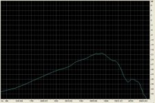
Here found it. I took the microphone output and first applied integration -20dB/dec to the whole thing and then applied a little boost at the high end from Wyber's plots to take out the slight roll-off that varies with spark energy. The curves simply slide so it becomes a one variable fitting problem.
Attachments

I see two things from that plot. First that the HF energy is limited. It seems like there is some physical property preventing energy above some slew rate in the plots? Would it be the speed of sound or the lower limit of zero air pressure?
Second, why when I get an acoustic spark from a surge generator (6KV @ 3KA @100 uS) its really loud. It seems I don't need that much energy.
I'm not sure the spark is the best source when looking above 30 KHz.
A quick look for acoustic pulse generators found this oddity: https://www.acoustic-revive.com/english/roomtuning/rr-77.html which really asks more questions about the gullibility of audiophiles. And gadgets for testing oil wells and plumbing but otherwise nothing useful.
I see two things from that plot. First that the HF energy is limited. It seems like there is some physical property preventing energy above some slew rate in the plots? Would it be the speed of sound or the lower limit of zero air pressure?
I never got into the physics, there seems to be some complicated fluid dynamics going on as well as the problem can not assume that things are isothermal so the simple acoustic wave equations do not apply. I never had the energy to buy his book, https://en.wikipedia.org/wiki/Yakov_Borisovich_Zel'dovich which Wyber sites as his source.
I love it when the snake oil salesmen warn you about counterfeits.
You are right, here's my raw data. Beyond 20K things get very complicated the dip at 26k or so could be from the full solution which includes Bessel functions, I have no idea how Earthworks goes to 100k.
Attachments
Last edited:
thinking that arc intiation, discharge path could be variable with an air gap I searched "exploding wire" with acoustic terms:
http://scitation.aip.org/content/asa/journal/jasa/64/S1/10.1121/1.2003994
the article might be the right thing but the pdf is only a page of abstracts
http://scitation.aip.org/content/asa/journal/jasa/64/S1/10.1121/1.2003994
the article might be the right thing but the pdf is only a page of abstracts
B&K Aging
First step in my microphone checking process. I'm going through all the mikes I have and doing some verification.
Attached are two B&K calibration curves of th same microphone 31 years apart in opposite sides of the world using very different equipment.
The obvious take-away is that they do not change much. The sensitivity increased about .6 dB over 30 years but I doubt the original accuracy was that good. In any case B&K says to calibrate the 1/4" microphones with a pistonphone on the preamp before you use them. They are such a small capacitance (7 pF) that very little stray will alter the sensitivity.
However the curves are very consistent over 30 years. As reported earlier if its not been damaged its probably accurate. The charts show the pressure curve from the electrostatic actuator and the "calculated" curve for free field.
I'll scan the curve for the 4136 in a while so the difference can be seen.
Attachments
First step in my microphone checking process. I'm going through all the mikes I have and doing some verification.
Attached are two B&K calibration curves of th same microphone 31 years apart in opposite sides of the world using very different equipment.
The obvious take-away is that they do not change much. The sensitivity increased about .6 dB over 30 years but I doubt the original accuracy was that good. In any case B&K says to calibrate the 1/4" microphones with a pistonphone on the preamp before you use them. They are such a small capacitance (7 pF) that very little stray will alter the sensitivity.
However the curves are very consistent over 30 years. As reported earlier if its not been damaged its probably accurate. The charts show the pressure curve from the electrostatic actuator and the "calculated" curve for free field.
I'll scan the curve for the 4136 in a while so the difference can be seen.
Demian,
It is +/- 1 dB to 20,000 hertz, how can you live with that? 🙂 As my best system goes to 12,000 hertz where the capsule is still flat, you can send it to me...
Or perhaps offer it to the OP.
ES
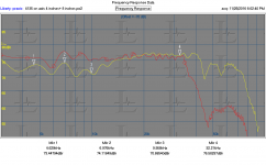
And here is my first test effort on this process. Source is a pioneer ribbon tweeter from an old box speaker. Microphone is the 4135 detailed above.
I made a cal file from the detailed data in the calibration report. I then set up the mike on axis with the tweeter at about 8" and made the first plot (the one that is really flat and stops at 35KHz. Then I moved the mike to about 4" from the driver and as you cans see not quite as flat but goes to 70 KHz.
Mostly this demonstrated that you can fool the system to get pretty much what you want. I did a lot of work on line arrays years ago and saw some of these effects then. The further you got from the array the more the HF interference degraded the HF response.
Attachments
EMX 7510 from ISEMCON is the best
http://www.isemcon.com/datasheets/iSEMcon EMX-7150-US.pdf
http://www.isemcon.com/datasheets/iSEMcon EMX-7150.pdf
buy it have fun - save money
http://www.isemcon.com/datasheets/iSEMcon EMX-7150-US.pdf
http://www.isemcon.com/datasheets/iSEMcon EMX-7150.pdf
buy it have fun - save money
Those look like a value. The Panasonic microphones are history so do you know who's capsules they are using? All of the electret measurement microphones are based on selecting capsules for performance. With the capsules in the $1 range there is lots of room for sorting if you have an efficient way to sort them.
I'll have more on the different B&K and similar microphones later today if all goes well.
I'll have more on the different B&K and similar microphones later today if all goes well.
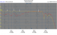
This is the 4135 (red) vs. a 4136 (yellow) in the same location (and preamp). The 4136 has no correction file and this shows the difference at high frequencies. I don't know why the difference at low frequencies but it can be ignored.
Next up will be the 1/2" mikes. I'll need to kludge a different stand/preamp so that will take some time.
Next up will be the 1/2" mikes. I'll need to kludge a different stand/preamp so that will take some time.
Attachments
First step in my microphone checking process. I'm going through all the mikes I have and doing some verification.
Attached are two B&K calibration curves of th same microphone 31 years apart in opposite sides of the world using very different equipment.
The obvious take-away is that they do not change much. The sensitivity increased about .6 dB over 30 years but I doubt the original accuracy was that good. In any case B&K says to calibrate the 1/4" microphones with a pistonphone on the preamp before you use them. They are such a small capacitance (7 pF) that very little stray will alter the sensitivity.
However the curves are very consistent over 30 years. As reported earlier if its not been damaged its probably accurate. The charts show the pressure curve from the electrostatic actuator and the "calculated" curve for free field.
I'll scan the curve for the 4136 in a while so the difference can be seen.
Impressive. I will save my $ for a B&K mic! Thanks for posting this.
- Status
- Not open for further replies.
- Home
- Design & Build
- Equipment & Tools
- ISO very accurate mic for speaker measurements