the maximum output current is not 5Apk for a 100W amplifier feeding an 8ohms speaker.
It is more likely to be at least 10Apk and can for very fast transients approach 25Apk.
I have read Bob Cordell and Otala on the theoretical possibility of peak currents in excess of nominal values but all the research I have seen has indicated it is not a problem in reality.
That makes your numbers look implausible to me, what is your reference or data?
The driver current does increase dramatically if you run the outputs into currents where hFE droops, so I don't, I simply double up the outputs.
If I believed in seriously supra-nominal current then I would do that here rather than have an over-specified driver to deal with a wretched 10% of nominal output performance.
But then it wouldn't be Damir's "Little Gem" - an amp with an excellent trade-off of simplicity and performance for normal conditions.
Best wishes
David
Thanks.
The mirror is best balanced when the base current of the VAS EF is equal to the total base current of the two CM transistors.
With the beta of the BC546B about half of the BC550C that means the emitter resistor of the BC456B should be about the same as for the CM.
The extra current should also mean it is a bit faster so less contribution to phase.
Best wishes
David.
Hi David,
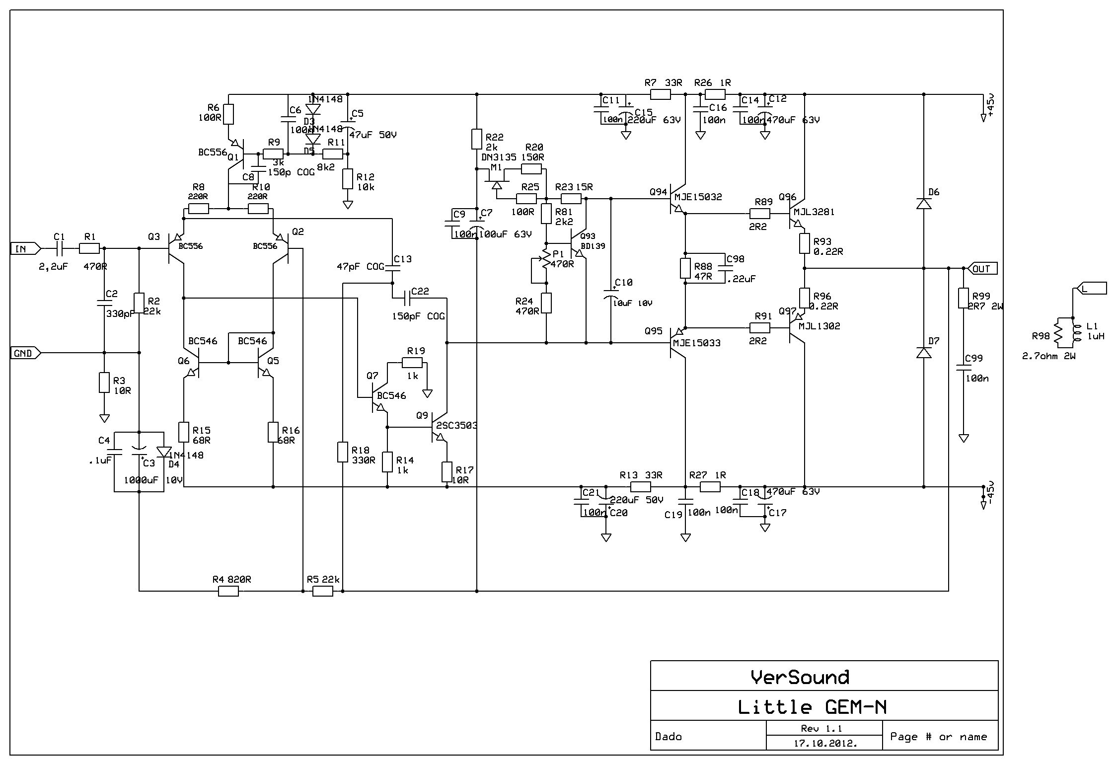
This is correct, but there is other thing to consider, how much the VAS EF loads the LTP. Simulation showed lowest distortion if EF resistor was 1k(CM end EF transistors are BC550C) and was going up by 2.2dB when used 100 ohm(in this case the VAS EF current was twice that of the CM's). I think that distortion was much important then small CM current asymmety(it was anyhow very small difference).
Regarding drivers AndrewT is right, 100 mA drivers have to low SOA even for this amp. Could work with +-30V of power supply i suppose. As all loudspeakers have impedance dips it should be workink with 4 ohm load too.
BR Damir
it is not even a theoretical debate...........the theoretical possibility of peak currents in excess of nominal values but all the research I have seen has indicated it is not a problem in reality.
That makes your numbers look implausible to me,...........
It is an actual and practical problem.
device IV = power dissipation.
That IV comes about from instantaneous Ic combined with instantaneous Vce.
Look at the instantaneous Pdiss of the output device and the driver device when delivering in phase voltage and current to a resistive load and the actual Ipk for a 100W into 8r0 load is indeed 5Apk. At that same 5Apk instant when the Vce is near zero volts the Pdiss is near zero.
Similarly when the output current is near zero the Vce when driving a resistive load is near max and again Pdiss is near zero.
The worst instant is when the Vce across the output device is roughly half the supply rail voltage and at this moment the current must be ~ half that 5Apk value.
All this changes when a reactive load is being driven.
The above is the case for constant or continuous sinewave signals.
The device currents and voltages into real speakers changes yet again when the signals are not constant and continuous sinewaves.
This time actual peak current exceeds the values that resistive loads draw.
All of this is well documented and is fact.
Start with esp's articles on speaker loads and the effects on amplifier output stages.
Then re-read Cordell and see if your alledged attribution still holds true.
Hi DamirThis is correct, but there is other thing to consider, how much the VAS EF loads the LTP. Simulation showed lowest distortion if EF resistor was 1k(CM end EF transistors are BC550C) and was going up by 2.2dB when used 100 ohm(in this case the VAS EF current was twice that of the CM's). I think that distortion was much important then small CM current asymmety(it was anyhow very small difference).
Yes, all these interactions needs to be considered and the optimum is not to alter one factor alone. My idea is that to increase the CM emitter resistors will reduce the noise but it can also help to improve the balance because it improves the ratio of CM emitter resistance to VAS emitter resistance.
Then there is a trade-off between speed in the VAS and load on the LTP
... 100 mA drivers have to low SOA even for this amp. Could work with +-30V of power supply i suppose. As all loudspeakers have impedance dips it should work with 4 ohm load too.
OK, if you want 4 ohm then the 2SC3503 is probably a little small.
But I did say "like" a 2SC3503. I will try a few others and see what looks nice.
Best wishes
David
Yes, of course, that's why I wrote that it needed a proper analysis of SOA.it is not even a theoretical debate.
...
the above is the case for constant...
That a reactive load line can be worse than a resistive load is not in dispute.
This time actual peak current exceeds the values that resistive loads draw....
This is the crunch. None of the load line analysis assumes that the peak current exceeds the value for a resistive load of the same impedance.
Of course one needs to allow for a load with dips below the nominal impedance.
But I think I don't need to allow for hypothetical "excess" currents on top.
So what is the data for the claim?
Best wishes
Maybe it's too late by now, but did you know thet "Little Gem" is the name of a **very** popular and famous guitar amp project?
So much so, that a Google search shows 312000 pages referring to it, either directly or indirectly.
https://www.google.com/search?num=2...XK4AOj4IHgBw&ved=0CCsQvwUoAA&biw=1024&bih=625
Sorry 🙁
So much so, that a Google search shows 312000 pages referring to it, either directly or indirectly.
https://www.google.com/search?num=2...XK4AOj4IHgBw&ved=0CCsQvwUoAA&biw=1024&bih=625
Sorry 🙁
Maybe it's too late by now, but did you know thet "Little Gem" is the name of a **very** popular and famous guitar amp project?
So much so, that a Google search shows 312000 pages referring to it, either directly or indirectly.
https://www.google.com/search?num=2...XK4AOj4IHgBw&ved=0CCsQvwUoAA&biw=1024&bih=625
Sorry 🙁
Thanks for the information, I did not know, hope the name is not protected. This one is realy little, and mine could be used for very good guitar amp(with proper preamp part).
Fine with me.
No, not registered (I think) and not my problem, just wanted to warn you because somebody interested might search and not find you.
*Maybe* you should start calling it "Little Gem Hi Fi" or something, so those searching for that string find you at once.
You know search engines are powerful but sort of dumb.
Good luck 🙂
Fine with me.
No, not registered (I think) and not my problem, just wanted to warn you because somebody interested might search and not find you.
*Maybe* you should start calling it "Little Gem Hi Fi" or something, so those searching for that string find you at once.
You know search engines are powerful but sort of dumb.
Good luck 🙂
It looks that searching is not important in this case as no one showed interest to build this amp, that's real pity.
No interest?
This new thread already has 89 answers !!!
Give it time 😉
It is not new, from October last year.
I'm reviving this thread about Dadod's very interesting amp which I've thought seriously about several times, following his comments about its sound quality. We are both old enough to know that our hearing is no longer ideal so I tend to regard claims about SQ with suspicion but in this case, I am going to get around to building it for myself - when the bench is clear of junk, at least 😱.
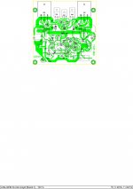
Apart from needing a mask of the PCB pattern, a parts issue that I have regards the SMD depletion mosfet for C7, the bootstrap capacitor. I'd like to use a common thru-hole DN2530 type and I assume it will be ok but would like to check whether adjustments are needed.
Also, since it wasn't discussed as far as I could see, would you like to explain the mosfet operation and need here?
No idea at this point, Luke. ' just clearing any obstacles first.....are you etching or getting boards made?
I'm reviving this thread about Dadod's very interesting amp which I've thought seriously about several times, following his comments about its sound quality. We are both old enough to know that our hearing is no longer ideal so I tend to regard claims about SQ with suspicion but in this case, I am going to get around to building it for myself - when the bench is clear of junk, at least 😱.
Apart from needing a mask of the PCB pattern, a parts issue that I have regards the SMD depletion mosfet for C7, the bootstrap capacitor. I'd like to use a common thru-hole DN2530 type and I assume it will be ok but would like to check whether adjustments are needed.
Also, since it wasn't discussed as far as I could see, would you like to explain the mosfet operation and need here?
The mosfet operation (depletion mode) was discussed in mine other thread. It is just CCS and it gives combination of CCS and bootstrap VAS, and I never saw anything similar used before.
If you like to build this amp here is last layout in pdf. In my prototype I used older layout, so it needs check and you can change mosfet from TO220 to TO92 type.
Damir
Attachments
Last edited:
Thanks Dadod, for your quick reply and helpful post of the latest PCB layout 🙂
If others are tempted to etch some extra boards or have a economical number made and share the cost, please post your interest.
If others are tempted to etch some extra boards or have a economical number made and share the cost, please post your interest.
Congratulations, you're design is very good amplifier. This amp can do a bit better. Look at R5L1. This circuit will add depth NFB.This amp I called “Little GEM”, very simple circuit with TMC(with a twist) and very low THD.
Attachments
Thanks Dadod, for your quick reply and helpful post of the latest PCB layout 🙂
If others are tempted to etch some extra boards or have a economical number made and share the cost, please post your interest.
Ian, you have PM.
Damir
- Status
- Not open for further replies.
- Home
- Amplifiers
- Solid State
- Little GEM