Hello, i'm building active subwoofer with FLI" 300W, 4 ohm speaker.
Sealed box, powering it with TDA7293 x3 parallel(these from ebay).
What i need is filter, ofcourse. I've ended up with these two:
P48 Sub-Woofer Controller (Rev-A)
Low pass filter - Subwoofer :: circuit diagrams
And i'm not sure, which one i should choose. Seems like 1st one has phase and gain controls, while the other has freq cut-off and gain controls. Which one would be better for sound quality(meaning nice low freq), or should i make both, and compare them 😕
Also, i would like to make over-voltage protection for my subwoofer amplifier input(in case filter goes down, it could feed +-12V into amplifier's input..?) Something like: http://1.bp.blogspot.com/-yvrNe0grMz0/U8K40NUUg3I/AAAAAAAADSA/YjH5BSjBbzc/s1600/vprotection.png?
Thanks
Equaliser P48 from Rod Elliott's site is very special (ELF by Long and Wichersham) and not a good match for your 12" car subwoofer.
You need something like second equaliser, but search further for better one, like this:
http://www.lcaudio.com/pdfs/subfilter.pdf
You need something like second equaliser, but search further for better one, like this:
http://www.lcaudio.com/pdfs/subfilter.pdf
In this circuit, i've noticed that Fcutoff potentiometer is 4 channel. What if 200k dual-channel would be used? Would that affect anything?
Instead of one four-channel 100k, use TWO 100k dual channel, but set it to be identical (measure it) for the desired resistance/frequency.
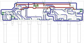
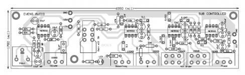
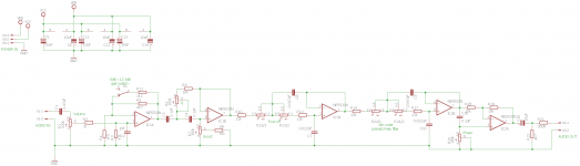
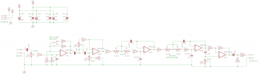
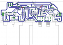
Alright, so i've redrawn it in eagle and made pcb.
Yeah, seems like i should go with 4-chan pot, since now there is too many of them... And it takes space.
Anyway, any recomendations about pcb design? I might make this as 1-layer pcb, power lines would have 'jumpers' at some places.
Yeah, seems like i should go with 4-chan pot, since now there is too many of them... And it takes space.
Anyway, any recomendations about pcb design? I might make this as 1-layer pcb, power lines would have 'jumpers' at some places.
Attachments
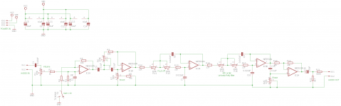
So in my schematic:
R5 -> 4k7
R4 -> 1k5 ?
Gain should be ~4.13.
Also, that gain x10 switch should be removed, and R4 goes to ground, or i'm wrong?
R5 -> 4k7
R4 -> 1k5 ?
Gain should be ~4.13.
Also, that gain x10 switch should be removed, and R4 goes to ground, or i'm wrong?
sub filter 😉
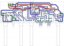
Thanks. Just now i realised, that i've used single-channel pots, where i could use dual-channel... Now pcb is way smaller.
Attachments
When the gain switch is closed, the NFB loop is operating and you get a gain = 4k7/1k5 + 1 = 4.13times (+12.3dB)
When the switch is open the NFB loop is not operating and the opamp acts as a Follower/Buffer. Now the gain is +0dB
If you also add in a plugable 2k2 parallel to the 4k7, you get a gain of +6dB switchable back to +12.3dB, when the 2k2 is opened.
When the switch is open the NFB loop is not operating and the opamp acts as a Follower/Buffer. Now the gain is +0dB
If you also add in a plugable 2k2 parallel to the 4k7, you get a gain of +6dB switchable back to +12.3dB, when the 2k2 is opened.
When the gain switch is closed, the NFB loop is operating and you get a gain = 4k7/1k5 + 1 = 4.13times (+12.3dB)
When the switch is open the NFB loop is not operating and the opamp acts as a Follower/Buffer. Now the gain is +0dB
If you also add in a plugable 2k2 parallel to the 4k7, you get a gain of +6dB switchable back to +12.3dB, when the 2k2 is opened.
So you mean like this? Well thats better than 0dB / 12.3dB gain switch.
By the way, what's the purpose of Q (R6 in schematic) ?
Attachments
R6 & R7 vary the roll off frequency of the high pass filter. This protects the bass driver from over excursion when you apply that +6dB or +12.3dB gain stage that you probably don't need when you already have +6dB from the bass summimg channel to input to your bass only speaker.
That would need a protection "system".
Many professional PA rigs include a system to ensure the paying audience hear the audio even though an idiot operator mis-sets the controls.
Many professional PA rigs include a system to ensure the paying audience hear the audio even though an idiot operator mis-sets the controls.
- Home
- Source & Line
- Analog Line Level
- Active subwoofer filter