As far as I'm concerned if people are still suggesting dual horn subs it's not solved.
Is it possible to build stereo bass horns, while also minimizing lobing issues? What if I built (qty 4) 1/4 space bass horns (each mouth sized roughly 14 feet tall, 8 feet wide), and joined all four side-by-side, to form an overall horn mouth of 14 feet tall & 32 feet wide. This seems big, but it's really not - it's roughly the same size as my shop's garage doors. The left two horns would make up a half-space stereo bass horn channel, and the right two horns would make up the other channel. Assuming most lower frequencies are recorded mono anyway, this horn would act more like a line of subs, while still providing me with full stereo separation (when stereo signals are present within the horn's band-pass). Another plus, is that I'd be installing drivers into four smaller horns, in lieu of just one big one (easing the clutter within the throats)
Thoughts?
Last edited:
I know about ITD and ILD and would be surprised if anyone on this forum didn't. Some, like me, may have read up on it a bit, and others may have gathered their knowledge from Wikipedia, but I am sure all are familiar with the concepts.
What I am completely unaware of, is of any literature where precedence of either over the other is investigated in the case of conflicting cues. Therefore, I am curious as to the origin of your knowledge.
What I am completely unaware of, is of any literature where precedence of either over the other is investigated in the case of conflicting cues. Therefore, I am curious as to the origin of your knowledge.
Weltersys seem to be arguing that OP's goal of a small audience area is dumb, so he seems to want to set it up for a much larger area using dual subs like a concert venue that needs to serve a huge audience area with even spl, which is somewhat at odds with even coverage and lobing considerations.
well, as you stated, Art's comments are not very clear, but I don't suppose he would vote for widely spaced stereo subs. Where he's coming from (big outdoors productions) a row of subs across the front of the stage is the norm.
Nothing is solved until OP drags his subs out and actually tests dual subs spaced at 60 feet center to center.
just saying OP has stated repeatedly he has been convinced to build one big horn instead of two widely spaced. 🙂
I know about ITD and ILD and would be surprised if anyone on this forum didn't. Some, like me, may have read up on it a bit, and others may have gathered their knowledge from Wikipedia, but I am sure all are familiar with the concepts.
What I am completely unaware of, is of any literature where precedence of either over the other is investigated in the case of conflicting cues. Therefore, I am curious as to the origin of your knowledge.
I wasn't aware either before this discussion prompted me to google on this topic 🙂
Did you see the link? I added it to my previous reply afterwards....
Though the two main channel woofers are going to engage the same room modes, with the same entry plane with regard to height and length of the room, and the same width modes with different but symmetrical entry planes, the point would be that bass is omnipresent in the room upon the point of perception of these bass tones. The concept of directivity (individually at least) at these low frequencies in a room doesn't hold water. I've tried analysing this from several points of view and the outcome is always the same (quantity and distribution within the room, complex sum of the input etc).true. GM neglected to specify if he was suggesting one or multiple subs. i interpreted his statement as the former.
Before one does their head in or resigns to blind faith it is comforting to know that this perception of image independently reduces the issue.
As an example you might run main channel woofers (not producing midrange) in mono, and panned kick drum fundamentals will still marry up with the stereo signal.
Is it possible to build stereo bass horns, while also minimizing lobing issues? What if I built (qty 4) 1/4 space bass horns (each mouth sized roughly 14 feet tall, 8 feet wide), and joined all four side-by-side, to form an overall horn mouth of 14 feet tall & 32 feet wide. This seems big, but it's really not - it's roughly the same size as my shop's garage doors. The left two horns would make up a half-space stereo bass horn channel, and the right two horns would make up the other channel. Assuming most lower frequencies are recorded mono anyway, this horn would act more like a line of subs, while still providing me with full stereo separation (when stereo signals are present within the horn's band-pass). Another plus, is that I'd be installing drivers into four smaller horns, in lieu of just one big one (easing the clutter within the throats)
Thoughts?
8 feet would mean that lobing/comb filtering between the discrete horns would set in around~ 143 Hz.
In general, regardless of xover point, this kind of approach appears like a very good compromise to me.

Hi all,
A single sub setup with an 'empty space' between L&R and the sub more than 1/4WL of the crossover frequency you have 3 point sources at the crossover.
Regards,
Djim
That's just one of the reasons you need a low crossover point.
But as I've pointed out several times now you can't get the mains any closer to the sub horn than the OP is currently proposing unless you put the mains inside the horn. So what's your solution?
... localization definitely happens based on cues in the whole auditory spectrum of human hearing, not just around 80 -120 Hz.
There is no localization at very low frequencies. Localization starts to happen around 80 - 120 hz. Anywhere north of 120 hz localization becomes pretty easy, especially when you are talking about subwoofers which are still putting out sound well past the crossover frequency unless you have a brick wall filter, and which are producing distortion.
Is it possible to build stereo bass horns, while also minimizing lobing issues?
It's always about center to center distance and wavelengths.
Sim it up in Direct and find out.
well, as you stated, Art's comments are not very clear, but I don't suppose he would vote for widely spaced stereo subs.
Actually I think he did. It's what he runs in his current job, mains on top of subs widely spaced. And there's no real "norm" in large concert setup. I've seen rows, clusters, vertical arrays and flown subs.
There is no localization at very low frequencies. Localization starts to happen around 80 - 120 hz. Anywhere north of 120 hz localization becomes pretty easy, especially when you are talking about subwoofers which are still putting out sound well past the crossover frequency unless you have a brick wall filter, and which are producing distortion.
🙄
well, the point you consistently fail to acknowledge, is that this only applies if you are listening to the subs on their own. As soon as you switch on your mains, there will be a ton of directional cues that will overpower the directinoal cues from the sub. The mains will also overpower what little higher frequency information comes from the sub above the cutoff frequency. After one octave the sub is down AT LEAST 12 dB in relation to the mains, and even more for higher order crossovers.
In a room, if the sub is clean (free of hiss and distortion), the filter slopes sharp, and the source is music, you can put your sub ANYWHERE and crossover as high as 130 Hz with no harm to stereo imaging. Lots of people who have tried it will tell you so.
But with a system with favourable geometry (mids and tweeters flanking the horn), I bet you could go to 200 Hz or higher and be just fine too. Not many people can testify on the subject (how high can you go when geometry favourable) because the object of the exercise is to be unrestricted as to where you place the speakers.
In a lab using pure tones and systems of unknown cleanliness, you can guess location correctly (or roughly so) about 51% of the time as low as 80 Hz, maybe, when that is your only task in life at that moment, I read.
Just plain ill-considered to take a proper high-class instrument like a true horn and cut it off as low as 80 Hz and pass the L and R signals on to inferior devices.
Too many people quoting inapplicable studies in "psychoacoustics" who are unqualified in both "psycho..." and "acoustics".
Time-algnmen is the big problem, not the theoretical nit-pick of losing diagrams at DISCRETE frequencies.
BTW, can somebody please post the RTAs for some representative drum kicks. About time all the ardent posters started knowing what they are talking about.
B.
Last edited:
@ just a guy & GM
Here's why it appears that F Low = (Qts x fs) / 2 appears odd, to me !
For eg - Qts = .3 fs = 36 Fl = 5.4Hz = Extremely low !
But that result isn't substantiated with Any other factors taken into consideration. Eg, - ?db, box size, box design, ported or not, etc etc.
Similar, not the same, questions apply to to F High = (2 x fs) / Qts
For eg - Qts = .3 fs = 36 Fl = 240Hz = Not that high
I'd like to know how those formulas could be usefully used in making an informed judgement when choosing drivers ?
Nice bd-design link 🙂
Yes, it's extremely low, I told you Fl isn't usually a problem.
On the other hand Fh is more important as you frequently see people trying to push an enclosure's bandwidth further than the driver's mass corner really wants it to go. As you can see just in the sims in this thread, OP's very light cone (low Mms) with strong motor (high Bl, low Qts) exhibits extremely high frequency response while the Labhorn doesn't. This is partly due to the driver and partly due to the horn flare.
Fh is the reason the driver can play high frequencies. The horn's contribution is the bandwidth it's designed for.
If you read through any number of Leach's or Keele's horn design papers this stuff becomes more clear.
When you are not making horns using the horn math (massively undersized horns designed using Hornresp sliders) or don't need the full 3 octaves a horn can provide then this stuff isn't that important, although you should always keep an eye on Fh just to make sure the driver is suitable for the application even if you can work around it.
Last edited:
Here's an example of why it's important. Ever seen a flh with 5 octaves bandwidth (actually 6 octaves if it's +/- 6 db). Here's one.
This is just an paper example because it's not practical (compression ratio is a bit over 13:1 - that doesn't really matter because pressure are velocity are remarkably low but there would never be any practical purpose for something like this) but this is a window into what is possible if you choose the right driver and put it in the right horn.
This is the 12 inch B&C that OP originally selected.
Fl = (Qts x fs) / 2
= (0.17 x 40) / 2
= 3.4 hz (which means I could have tuned this example a lot lower but there's no point since you can't see below 10 hz in Hornresp)
Fh = (2 x fs) / Qts
= (2 x 40) / 0.17
= 470 hz
You can see pretty clearly that the Fh formula for the driver's high frequency mass corner pretty accurately predicts the horn's upper bandwidth, response starts dropping off right around 470 hz (I kept it propped up a bit past 470 hz by playing with the throat chamber a bit). And it's only about 5 db down at 1khz.
So this is why it's important - if you want to push the bandwidth limits as far as you can you need the right driver. Try this with the usual B&C 18 inch suspects with heavy cones and see if you can push them anywhere near this high. But it's also important to note that super extended bandwidth isn't really all that valuable in most cases, certainly not for subs.
An externally hosted image should be here but it was not working when we last tested it.
This is just an paper example because it's not practical (compression ratio is a bit over 13:1 - that doesn't really matter because pressure are velocity are remarkably low but there would never be any practical purpose for something like this) but this is a window into what is possible if you choose the right driver and put it in the right horn.
This is the 12 inch B&C that OP originally selected.
Fl = (Qts x fs) / 2
= (0.17 x 40) / 2
= 3.4 hz (which means I could have tuned this example a lot lower but there's no point since you can't see below 10 hz in Hornresp)
Fh = (2 x fs) / Qts
= (2 x 40) / 0.17
= 470 hz
You can see pretty clearly that the Fh formula for the driver's high frequency mass corner pretty accurately predicts the horn's upper bandwidth, response starts dropping off right around 470 hz (I kept it propped up a bit past 470 hz by playing with the throat chamber a bit). And it's only about 5 db down at 1khz.
So this is why it's important - if you want to push the bandwidth limits as far as you can you need the right driver. Try this with the usual B&C 18 inch suspects with heavy cones and see if you can push them anywhere near this high. But it's also important to note that super extended bandwidth isn't really all that valuable in most cases, certainly not for subs.
Last edited:
Is it possible to build stereo bass horns, while also minimizing lobing issues? What if I built (qty 4) 1/4 space bass horns (each mouth sized roughly 14 feet tall, 8 feet wide), and joined all four side-by-side, to form an overall horn mouth of 14 feet tall & 32 feet wide. This seems big, but it's really not - it's roughly the same size as my shop's garage doors. The left two horns would make up a half-space stereo bass horn channel, and the right two horns would make up the other channel. Assuming most lower frequencies are recorded mono anyway, this horn would act more like a line of subs, while still providing me with full stereo separation (when stereo signals are present within the horn's band-pass). Another plus, is that I'd be installing drivers into four smaller horns, in lieu of just one big one (easing the clutter within the throats)
Thoughts?
The simulations imply it would be fine: based on the nice-looking images bob4 posted, a horizontal line of subs doesn't have any prominent nulls*. I had a quick go with that Danley software, to confirm. In my tinkering, it didn't seem to require a huge line - 4 sources were enough.
If your experience at big gigs is a worst case scenario, it also implies that such an array would be fine.
As previously covered by JAG (posts 133-), horn mouths sum when in arrays. Any mono signal would "see" the total mouth size. A purely R or L channel signal would "see" a half-sized mouth, so you'd have marginally less bass extension for tones that only came from one channel.**
I was speculating / suggesting 8 cells, so there would be 1 driver per throat (or mini-horn). With such a layout, you could pick one pair to go ~an octave higher than the rest. Again, a quick go with the Danley software made that seem OK.
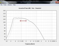
This sim image here is basically a rehash of JAG's post 136, except I'm showing 1 vs 4 (rather than 1 vs 8), and I think he forgot to change rear chamber size, thus my 1/4 and full versions look slightly more alike than his 1/8 and full size sims.
This shows:
- 15" drivers
- Horns 4m long
- Mouths 1.2mx1.2m (i.e. each mini-horn is 4'x4'. A quad would have an 8'x8' mouth***)
Shown is the output of a quad, overlaid on the output of a single cell. Based on this sim, if the entire quad was operating up to ~80Hz, and just one driver / mini-horn kept going for another octave or two (the marked range), the sound quality would stay consistent.
The other image is just a hack-up of one of the pdfs that tb46 has supplied (post 623); I re-scaled his image (which showed 8 longer, skinnier horns) to roughly illustrate my sim's dimensions.
*I'm guessing the mechanism behind this is: simulating point source L and R speakers gives a simple pattern of large nulls (and peaks). When there are multiple sources, there is a complex pattern with many nulls (and peaks), and these don't broadly sum at any location.
**an ideal system would lose 3dB when a 40Hz tone was panned hard right (rather than playing from both channels). A horn array as described might lose another 0.5dB when panned hard right. That is: a difference that would be difficult to detect, under ideal test conditions.
***a shipping container. My go-to size: easy to visualise, and the option I would use if I was to do it myself.
Attachments

Hi hollowboy,
Post #696: "...The other image is just a hack-up of one of the pdfs that tb46 has supplied (post 623); I re-scaled his image (which showed 8 longer, skinnier horns)...
Just to clarify, those were horn throats (maybe better called horn input couplers) that than would join into another 16ft of horn before reaching the full size horn mouth. It was to show that it is comparatively simple to keep the drivers directly coupled to the end of the horn/throat (Hornresp Nd), and that it is not necessary to use offset drivers. Others have used this method successfully for higher frequency horns, so we know it will work without problem at low frequencies.
Regards,
That's a lot of length!Just to clarify, those were horn throats (maybe better called horn input couplers) that than would join into another 16ft of horn before reaching the full size horn mouth.
Sorry, I missed that intention, I just liked the picture enough to steal it 🙂It was to show that it is comparatively simple to keep the drivers directly coupled to the end of the horn/throat (Hornresp Nd), and that it is not necessary to use offset drivers. Others have used this method successfully for higher frequency horns, so we know it will work without problem at low frequencies.
On 2nd thought, single horn components intended to play ~an octave higher would beam too much horizontally, as pictured.
Easy fix: making the mouth rectangular + a mixed flare (flat top & bottom, curved sides), rather than what I pictured (stole), would give a wider horizontal pattern.
In Hornresp:
Schematic Diagram
File - Export - Horn Data - Rectangular Horn
Width Flare "Conic"
...then play with the mouth ratios and "preview" the two views to see the shapes & mouth angles
If the hottub is in between them then comb filtering won't happen, will it (if a tree falls in the forest..)?As far as I'm concerned if people are still suggesting dual horn subs it's not solved.
There are no walls to reflect, so does lobing matter?
If the hottub is in between them then comb filtering won't happen, will it (if a tree falls in the forest..)?
There are no walls to reflect, so does lobing matter?
This:
http://www.diyaudio.com/forums/subw...bass-horn-design-question-16.html#post4860708
"The second purpose of the system is to entertain guests (aka party)"
...so more than 1 listening location.
- Home
- Loudspeakers
- Subwoofers
- Concrete Bass Horn Design Question