@ just a guy
You can add a baffle either side of the enclosure in HR via the Wavefront Simulator. Whether or not this will be helpful to you and/or others ? Just thought i'd mention it, in case 😉

@ Entropy455
The BSS stuff is top notch, & it will do ALL what you want, & a whole lot more ! You can download the London Architect software for Free & tinker with it right now 🙂
You can add a baffle either side of the enclosure in HR via the Wavefront Simulator. Whether or not this will be helpful to you and/or others ? Just thought i'd mention it, in case 😉
@ Entropy455
The BSS stuff is top notch, & it will do ALL what you want, & a whole lot more ! You can download the London Architect software for Free & tinker with it right now 🙂
Attachments
Being a digital in/out device, the Soundweb has caught my attention. I will have to spend some time on this one - as there's a lot of configuration options here (downloading the technical specifications now). This is going to sound crazy, but I actually still hold the qualification at work to pot & polish optic cables. You can't get a much cleaner signal coupling than light! But I digress. Is there a particular Soundweb model number you’d recommend?
I've only worked with older soundweb models. What I can tell you about the principle is that the soundweb works a bit like a "DSP Lego box", in which you custom-design the signal path from functional units according to your needs in a PC software with a graphical editor reminiscent of MAX/MSP.
For now the main issue I think is single vs dual separated subs.
ok, so I did a second simulation (let's call that simB)with the DBH218s spaced 8 m apart, stacked 4 high, and compared that to the bass response of the DBHs stacked in one 8m long row (simA).
I decided to use the microphone placement feature in Direct, because you can have multiple mics and plot their frequency responses. This makes it easier to see what's going on. The 3d view is sexy, but you have to make a shitload of screenshots.
So here it goes:
simA, 8 pcs of DBH218 laying on the ground in a row. Four mic positions: 1) 2m away dead center of stack 2) 8m away centered 3) 8 m , 2m to the right side 4) 8 m, 3m to right 5) 8 m, 4 mto right
An externally hosted image should be here but it was not working when we last tested it.
simB 8 pcs of DBH218s spaced 8 m apart, stacked 4 high. Same mic positions, black is 2m
An externally hosted image should be here but it was not working when we last tested it.
Sorry can't be bothered to verify which colour is which mic position. I think that information is not that relevant, the plots speak for themselves. 🙂
I think the DBHs are great for this, because they are frontloaded like the horn entropy wants to build, and rather big with 1,1m width, which makes it easy to simulate one large radiator.
sorry, my pic for simB was missing the 8m, 4m right mic (light blue trace) , here is another graph with it:
An externally hosted image should be here but it was not working when we last tested it.
Your system is likely to have location challenges. Hard to get steep enough crossover slopes analog-ly to avoid the horn revealing its location. Likewise for noise and distortion originating in the horn.I have an active analog 3-way crossover on my Wife's stereo now, and I love it - very clean - works well.
Gosh, I feel so much better informed now about lobing of pure tones. Too bad it has no relevance to your build. There are a whole bunch of factors leading to constructive and destructive wave geometry of pure tones. And the pretty pictures of sound loudness would shimmer and sway and be in technicolour if you could just animate them as they happen in real music. But on music, undetectable by ear.*
Ben
*Anybody notice that Danley has his own commercial reasons for scaring everybody about lobing of line sources?
Last edited:
Your system is likely to have location challenges. Hard to get steep enough crossover slopes analog-ly to avoid the horn revealing its location.
what is this vague statement supposed to mean?
localization cues coming from the mains will totally dominate perceived localization. More than 50 years of psychoacoustics research has consistently confirmed this.
Likewise for noise and distortion originating in the horn.
yep, if the horn farts and distorts, THAT will be localizable. You got that right.
Gosh, I feel so much better informed now about lobing of pure tones. Too bad it has no relevance to your build.
Are you thick? Can't you read a frequency response graph? You can easily see in the two simulations that I posted that there will be areas with 10 - 20 dB notches in the bass range due to comb filtering. Of course it has relevance. It's the reason why two spaced sub bass horns are a bad idea.
There are a whole bunch of factors leading to constructive and destructive wave geometry of pure tones.
BEEEP! WRONG! Like JAG pointed out, it's purely a matter of source spacing and triangulation. Name one of your supposed "bunch of factors".... I'm sure you can't come up with one
*Anybody notice that Danley has his own commercial reasons for scaring everybody about lobing of line sources?
Danley is not scaring anyone about lobing, our discussion happens to be about lobing. He is providing a system design tool for free.... 😕
I'm sorry to say, but I don't understand why you keep making pompous and deliberately obscure comments laced with outrageuosly nonsensical statements that contradict basic acoustics.... 😕

Next VERY IMPORTANT conceptual design question:
I want a rectangular mouth. Is there a rule-of-thumb for the aspect ratio? i.e. 3:1 width to height, or 21:8 width to height. Specifically, are there ratios that should be avoided? Assume my horn’s mouth area is 20.9 m^2, or 225 ft^2 (go big, or go home. . . . right?) Let’s say I choose an arbitrary 10 foot tall mouth. The mouth width would then be about 22.5 feet wide – making the aspect ratio 9:4
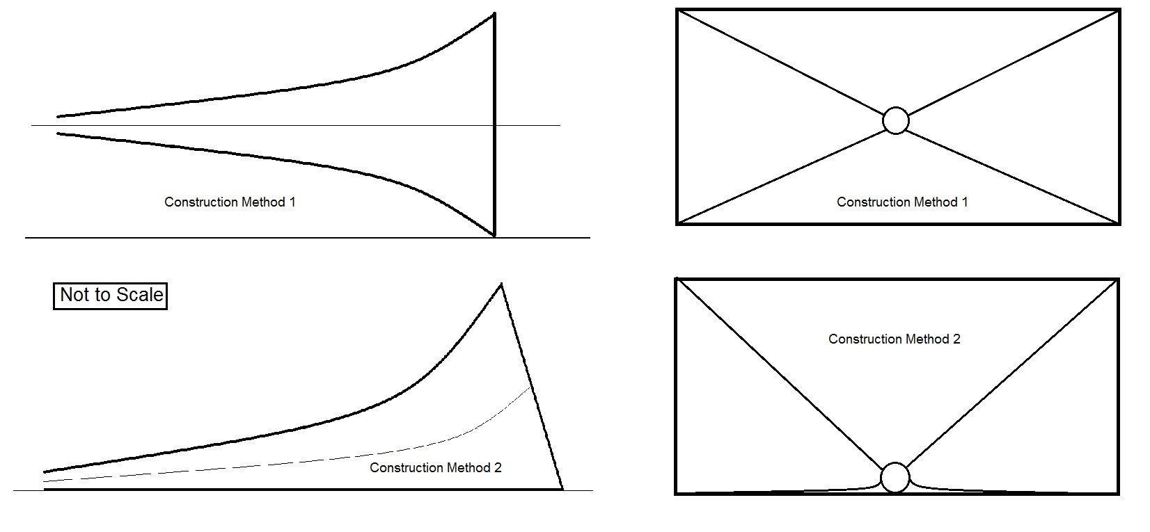
Construction method 1: I’m assuming I’d shoot a straight line from the center of the throat, to the center of the mouth (presumably parallel with the earth) – then I’d frame my concrete forms to match the exponential area expansion – while maintaining the 9:4 ratio. (i.e. for each cross-section, the vertical walls are equal distance from the centroid, and the horizontal walls are also equal distance from the centroid – all while maintaining the 9:4 ratio throughout. I understand that I must transition to round in the throat – but I don’t want to take this off topic. So in construction method 1, the horn is a straight-shot, and rainwater will not collect in the bell of the horn. .. .
Construction method 2: I could theoretically make the bottom wall of the horn flat with the ground. For this scenario, the centroid line down the horn would not be straight, however the 9:4 aspect ratio would be maintained. Or said another way, the vertical walls would expand identical to method 1, however the overhead of the horn would rise at a greater rate (as measured from the ground datum) – while still maintaining the 9:4 aspect ratio. Would this still sound as good as method 1? It would sorta be the same horn, just with a curved center-axis line. I worried that instead of loading the wave along the half-space, I'd be shooting sound towards the sky. What I like most about method 2, is that people could actually walk into the horn, without climbing up an exponential curved surface. What I don’t like, is the horn has the potential to collect wind-driven rainwater. Thus I’d probably build it with a few degrees down-angle. Question: am I loosing anything by doing method 2? There’d be no parallel walls, however I would have one flat wall, down practically the entire length of the horn. The horn would literally be resting on the half-space plane.
Note: a 10-foot x 22.5-foot rectangular mouth is doable (from an ACI-318 perspective – i.e. I can safely build this big of horn from cast (non-prestressed) reinforced concrete. it’s doable. . . .)
Opinions???
One more note: I would describe Method 1 as an ideal "straight" exponential horn. My gut tells me this is the horn I should build. However I am wondering if there are any advantages in going with Method 2 (i.e. sound aspects only, and specifically not construction difficulty aspects). I'm still a bit fuzzy on how to properly utilize half-space loading with a bass horn. . . .
Last edited:
ok, so I expanded my simulations a bit......
I also found out by accident how to scale and zoom the frequency response window 😀
simC of 12 DBH218 in a row, same mic positions like before:
simD of two rows of 4 DBH218, spaced 8m apart, same mic positions:
so why is the response of simC (mono sub) better?
1) The shapes of the curves correlate strongly
Thus the bass range can be expected to sound and feel very uniform in the listening area without any dead spots or missing notes
2) consequently, EQ can be applied to voice the system (e.g. even out the 60 - 120 Hz hump)
3) The different mic positions exhibit decreasing level with increasing distance from the array
On the other hand simD shows
1) little correlation between mics
2) huge peaks and dips
3) huge level variations. For example the light blue line from a measurement point 8m away and 4 m to the left is louder than the black line which is only two meters away from the centerline. Yes. This means that close to the datum between the two horns it will be actually more quiet, whereas on axis of either left or right horn the bass will be louder.
I rest my case......
ADDENDUM:
This is how the power alley looks like at 80Hz....
simC
simD
I also found out by accident how to scale and zoom the frequency response window 😀
simC of 12 DBH218 in a row, same mic positions like before:
An externally hosted image should be here but it was not working when we last tested it.
simD of two rows of 4 DBH218, spaced 8m apart, same mic positions:
An externally hosted image should be here but it was not working when we last tested it.
so why is the response of simC (mono sub) better?
1) The shapes of the curves correlate strongly
Thus the bass range can be expected to sound and feel very uniform in the listening area without any dead spots or missing notes
2) consequently, EQ can be applied to voice the system (e.g. even out the 60 - 120 Hz hump)
3) The different mic positions exhibit decreasing level with increasing distance from the array
On the other hand simD shows
1) little correlation between mics
2) huge peaks and dips
3) huge level variations. For example the light blue line from a measurement point 8m away and 4 m to the left is louder than the black line which is only two meters away from the centerline. Yes. This means that close to the datum between the two horns it will be actually more quiet, whereas on axis of either left or right horn the bass will be louder.
I rest my case......
ADDENDUM:
This is how the power alley looks like at 80Hz....
simC
An externally hosted image should be here but it was not working when we last tested it.
simD
An externally hosted image should be here but it was not working when we last tested it.
Last edited:
....Ben
*Anybody notice that Danley has his own commercial reasons for scaring everybody about lobing of line sources?
Yup, just like the line guys have for telling us we can ignore them.
The proliferation of line array and the resultant sound quality has nearly stopped me from going to concert events and I live in a live music mecca, Las Vegas.
Ben you seem like a hearing is beleiving guy and I am reasonably sure that all you would have to do is attend one proper array vs point source shootout and you would would get it. When you walk around a stadium with a DSL system playing for the first time, you nearly can't believe what you are hearing it's so good.
In all threory, point source is the solution. The real world problem is how do you get a plus 140 dB SPL full range point source? Tom did it and that doesn't change the rules, it changes how we play the game.
Barry, who has no vested interest in DSL, has several large format sound systems and the real world experience that comes with them, and who like Art, uses what works.
All the best.
I'm still a bit fuzzy on how to properly utilize half-space loading with a bass horn. . . .

well, AFAIK the boundary has to be considered like a mirror. Impinging sound waves bounce off. This means that for each real source, the ground reflection acts geometrically like a mirrored copy of the real source, with the boundary itself as the symmetry axis. In other words this means, you can simply build half of construction model 1, slashed in half along it's centerline, with a flat floor. With the half space loading, the lower half of the horn will be added virtually. Did that make any sense?
EDIT: there is also no reason why the throat should be round. If you plan to use a big bunch of 18" woofers, it would make way more sense to make the throat a vertical slot. Maybe even have the horn have constant height, while providing expansion only with the side walls....
Last edited:

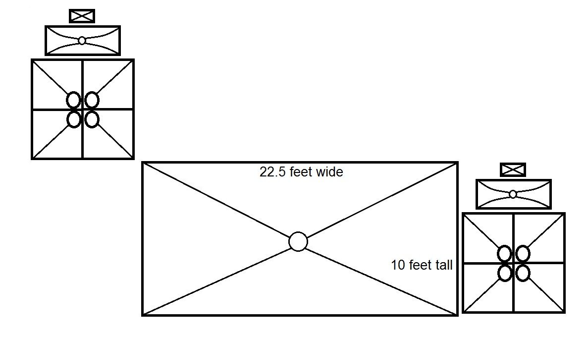
Next question. You guys are convincing me (quite well) that I should narrow my stereo spacing.
So I'm picturing myself building some kick horns (80 Hz cutoff), built around (qty 4) 15" drivers. My thought was to build 4 quarter space horns, and join them together to form one full-space 80 Hz horn. Do the kick horns need to be full-space? Or are they close enough to the ground to warrant a half-space design? Then I'd have one low-midrange horn, and one high-midrange horn.
As shown on the right, I could build a void into the wall, to house these horns - perhaps even put a door on it (I really like this idea - as I could put the stereo away by simply shutting a door). As shown on the left, I could place the horns on top of the wall.
If this was your decision to make, which configuration would you lean towards?
Note: I have not considered the SPL balance yet - I might need extra horns. This is general layout/conceptual system design question.
the boundary has to be considered like a mirror. Impinging sound waves bounce off. This means that for each real source, the ground reflection acts geometrically like a mirrored copy of the real source, with the boundary itself as the symmetry axis. In other words this means, you can simply build half of construction model 1, slashed in half along it's centerline, with a flat floor. With the half space loading, the lower half of the horn will be added virtually. Did that make any sense?
The sketch in construction model 1 is already a half-space horn (i.e. it's based on the area-expansion of a half-space horn)
I am having difficulty with the concept of taking a full-space horn, and "literally" slicing it in half, and setting it on the ground. Is that really the intended concept?
Assume for the moment (just to help me understand) - what if I were building a straight 1/8 space exponential horn into the corner of a room (a straight horn, punching in from outside). Shouldn't each wall of the horn still have a curved exponential surface? If three of the four sides of the horn were flat surfaces, I can't imagine this sounding good. . .
Last edited:
Maybe even have the horn have constant height, while providing expansion only with the side walls....
Practically every resource I've read states that parallel walls in a horn are less than ideal. Are you sure that having the roof & floor of my horn as parallel surfaces, is a good thing? This does not seem like a shape you'd get, from cutting a full-space straight exponential "ideal" horn in half.
Again, I'm not trying to argue, but rather to understand. . . .
BEEEP! WRONG! Like JAG pointed out, it's purely a matter of source spacing and triangulation. Name one of your supposed "bunch of factors".... I'm sure you can't come up with one
1. crossover phasing
B.
Last edited:
1. crossover phasing
B.
please elaborate? That's just a synonym for lobing/comb filtering. 😕
You guys are convincing me (quite well) that I should narrow my stereo spacing.
Well slow down on that. Mains spacing can be worked with and isn't the primary concern yet. I still haven't simulated anything other than what I showed so far, as I was waiting for you to acknowledge that you had even looked at the sims I provided so far. Once you decide for sure on single or dual subs the mains positioning sims can commence. As turk mentioned, a very steep crossover can cure a lot of comb filtering issues between the subs and the mains, so if you are prepared to use a very steep crossover the issue becomes mains directivity when positioning and pointing to cover your audience position, not so much comb filtering between the sub and mains. The thing I did sim looked bad mainly because of the dual subs, probably not so much because of the wide spaced mains, although I'd have to confirm that to see how much each factor contributed.
So I'm picturing myself building some kick horns (80 Hz cutoff), built around (qty 4) 15" drivers. My thought was to build 4 quarter space horns, and join them together to form one full-space 80 Hz horn. Do the kick horns need to be full-space? Or are they close enough to the ground to warrant a half-space design? Then I'd have one low-midrange horn, and one high-midrange horn.
When you choose Ang (1/2 space, full space) in Hornresp the sim is assuming that the horn mouth is flush mounted into the boundary. In the case of your big sub horn, the sim assumes the horn is buried in the ground and firing straight up, which both isn't possible (at least not practical) and makes the virtual mic position above the horn, not where the audience is.
If you want to get a better look at boundary loading issues, I've already showed you a super simple tool you can use.
The picture you drew isn't really to scale, but assuming the midbass horns are 80 inches tall, the center point is 40 inches. A boundary reflection from a point source 40 inches above the ground looks like this.
An externally hosted image should be here but it was not working when we last tested it.
As always, it's all about wave frequency lengths and distances. It doesn't matter how you design them, but once designed I would sim them in 1/2 space and in full space. The actual measurements of the thing you build will probably be somewhere in between. From this alone, it looks like it's going to be primarily full space though, as 80 hz looks to be in the transition zone and everything above that is full space (not boundary reinforced by the ground).
And in case it's not clear, the area in the graph (the frequencies) where you have the +6db boundary reflection is 1/2 space, the area in the graph that rides the 0db line is full space, and there's a transition region between the two.
Practically every resource I've read states that parallel walls in a horn are less than ideal. Are you sure that having the roof & floor of my horn as parallel surfaces, is a good thing? This does not seem like a shape you'd get, from cutting a full-space straight exponential "ideal" horn in half.
Again, I'm not trying to argue, but rather to understand. . . .
Parallel walls in a horn are bad - sometimes. If the distance between the parallel walls is small compared to the wavelengths in the passband then it doesn't matter. If the distance between the parallel walls is a significant fraction of the wavelengths in the passband it becomes a problem, and it's a problem that you can't simulate.
Here's Danley's notes on this issue from the Labhorn design notes.
Still more complication, at the point where the wall area is a significant acoustic
size, the sound pressure couples to the width mode resonance (caused by the parallel
walls) which puts the first in a series of notches in the response coming out of the
mouth. In this situation, there is a 1/2 wavelength standing wave with the pressure
maxima at the walls and velocity max in the center. Coupling to this mode saps off
energy at frequencies related to the N 1/2 wavelengths. Here, your horn mouth width
(where it has parallel walls) also kind of sets your upper frequency limit. For a 21
inch wide horn like the LAB sub, the first width mode notch should be in the mid 300's
which is a non issue.
Your horn is very large, so you don't want parallel walls. At the throat it doesn't matter because the throat dimensions are small, but further along the horn where the dimensions are large it's a problem.
Also understand that non parallel walls don't completely fix the issue either, they just spread the resonances out. Sometimes super high fidelity rooms are constructed so none of the walls are parallel. This doesn't get rid of the resonances, it just spreads them out so you don't get really huge spikes and deep notches at a few frequencies, instead you get lots of little bumps and little dips at a lot of frequencies, it's a smoothing and evening effect.
Last edited:
Maybe even have the horn have constant height, while providing expansion only with the side walls....
This is not a good idea for the reasons I just explained - a 10 foot distance between parallel walls all along the length of the horn is going to produce a strong width mode resonance that can't be simulated and it will definitely be low enough in frequency to be in a subwoofer's passband.
This is not a good idea for the reasons I just explained - a 10 foot distance between parallel walls all along the length of the horn is going to produce a strong width mode resonance that can't be simulated and it will definitely be low enough in frequency to be in a subwoofer's passband.
yeah, you're absolutely right with that one, that was a brain fart on my part.
- Home
- Loudspeakers
- Subwoofers
- Concrete Bass Horn Design Question


