Hi Dave, yes you are right! That was the reason for the shape of the curve.
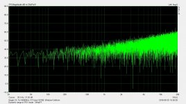
When I disable the mic cal, I get a flat curve. But I still don't understand why the level is around 130dB, and not at zero dB as shown in Arta manual page 59 (and elsewhere).
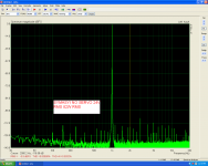
And when I disconnect the loopback, to measure noise floor, it looks wrong as well (see attached). I was expecting something like shown in this post: http://www.diyaudio.com/forums/multi-way/76977-arta-44.html#post4468748
When I disable the mic cal, I get a flat curve. But I still don't understand why the level is around 130dB, and not at zero dB as shown in Arta manual page 59 (and elsewhere).
And when I disconnect the loopback, to measure noise floor, it looks wrong as well (see attached). I was expecting something like shown in this post: http://www.diyaudio.com/forums/multi-way/76977-arta-44.html#post4468748
Attachments
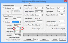
testing tascam 2x2
jvhb,
probably with your card is everything OK.
You just need to check off microphone control in Setup->Audio devices dialog box.
Then you will get FR results near 0dB line.
Ivo
jvhb,
probably with your card is everything OK.
You just need to check off microphone control in Setup->Audio devices dialog box.
Then you will get FR results near 0dB line.
Ivo
Hello Ivo, thanks for stopping by 🙂
Yes that fixed the level! 0 dB FR results now, and the noise floor test moved down to around -90 to -100dB. So one step forward 🙂
But the results from the noise floor measurements still look like the picture in post 481, and not a line curve like on page 60 in the Arta manual. Why is that?
Also, if you have any input on building a measurement box to work with a Soundcard integrated mic pre amp I would really appreciate it.. Se my question in post 478.
PS. I just purchased commercial ARTA license today - don't know if you have seen the order (or received notification) yet.
Noise floor measurement
For noise floor measurement manual shows results with 1/n octave smoothing and averaging.
Please, click right mouse button in FR window and set Frequency axis type to Octave smoothing and resolution to 1/3 octave.
Use at least 16 averaging.
License key has bee sent.
Ivo
For noise floor measurement manual shows results with 1/n octave smoothing and averaging.
Please, click right mouse button in FR window and set Frequency axis type to Octave smoothing and resolution to 1/3 octave.
Use at least 16 averaging.
License key has bee sent.
Ivo
Octave smoothing yes! I had overlooked that somehow. Now everything looks good! Thanks for your help. Next is the whole measuring box project and getting it to work (well) with the internal Tascam mic pre...
I'd like to post a general ARTA question and not take over the thread:
Does anyone know how to have more than one overlay with ARTA. Yes, I have a licensed copy.
I see how to 'set as overlay', save and load. But, I can only seem to ever get one overlay and then the 'magnitude'. Looking at color options, it shows all the color options for each overlay number.
I'm focusing on this in the spectrum analyzer function.
I have tried saving wave forms and loading, but it only ever displays (1) overlay and magnitude.
Hello,bump for post 486...
ARTA Help: 2 spectrum analyser 2.11 graph overlay
Besides the possibility to load as many overlays you wish and showing difference between magnitude and overlay, to my understanding only one overlay can be created in a graph.😉
Hi Ivo,
I have the following question. We have done anechoic decay measurements on a speaker with a FIR filter that can be switched in or out to turn back the phase shift caused by a first IIR stage with LR4 filtering. The measurements were made with the FIR filter out of the loop.
Now, the feedback we got is that because we did the CSD measurement in minimum phase mode, the decay is longer than it would have been in linear phase mode.
Of course, the pulse is stretched out in minimum phase, so this might conceivably be the cause of a longer measured decay, but I just don't know the guts of your program well enough so I am just guessing. Can I please ask what your take is on this?
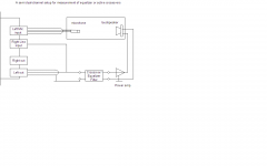
Measurement with equaliser/active crossover
Hi Vacuphile,
in attachment I give you shematic of measurement setup when you want to include response of active crossover/equalizer filter in the loudspeaker response.
If you make filters in digital domain, than you may expect large delay especially if you use FIR filters.
If I've understood You tried to compensate delay of IIR filter with FIR filter, so delay is very large. Also, long pre-ringing of FIR filter is hard to catch in CSD response.
Note:
I do not like your approach. Loudspeaker is not minimum phase system and equalizing it on axis may results with worse response off axis.
KISS!!!
Best,
Ivo
Attachments
RE:
Following last message.
I forgot to note that to keep measurement system calibrated you should set right channel preamplifier gain equal to 1/power-amp-gain.
Ivo
Following last message.
I forgot to note that to keep measurement system calibrated you should set right channel preamplifier gain equal to 1/power-amp-gain.
Ivo
Ivo,
This type of (extra) delay in the measurement loop highlights the issue I noted back near Post 308.
When inputting a relative delay in FR2 mode, that delay is implemented in the wrong leg of the measurement.
Even assuming a user was using a FIR filter with long delay, the displayed response could still be reduced to minimum-phase with an concurrent delay in the reference channel.
Cheers,
Dave.
That said, and for vacuphile's benefit, there is a psuedo work around to this issue.
Just reverse your input leads and make the measurement channel the reference channel (and vice-versa) and then input an appropriate delay (in milliseconds) into the Measurement Config box. That will allow you "back out" any latency in the DUT.
Cheers,
Dave.
Just reverse your input leads and make the measurement channel the reference channel (and vice-versa) and then input an appropriate delay (in milliseconds) into the Measurement Config box. That will allow you "back out" any latency in the DUT.
Cheers,
Dave.
Last edited:
Delay can be compensated
Hi,
delay can be compensated, indeed, but the problem is that lot of guys do not understand why ARTA uses zero delay position at sample position 300.
Here is the explanation:
Almost all today AD converters are sigma-delta converters with digital FIR antialiasing filtering. That filtering causes lags from 32 to 128 samples and to account for that lag ARTA records 300 samples before the "zero delay time".
In dual channel mode delay must be estimated as time interval from sample position 300 to beginning of the impulse response.
In single channel mode it is not possible to estimate initial time delay and ARTA puts the point near start of IR at sample position 300.
Best,
Ivo
P.S. I was also asked why there is possibility for only one overlay in Spectrum, FR1 and FR2 modes.
The answer is:
This version of ARTA keeps compability with Windows XP, which is generaly used on slow computers with only 256k of memory. Most of that computers cannot process more overlays in reatime mode.
@ iMat
I know quite a few people who still use & are very happy with XP, myself included 🙂 Most have between 1Gb - 2Gb of RAM. I have 2Gb !
I know quite a few people who still use & are very happy with XP, myself included 🙂 Most have between 1Gb - 2Gb of RAM. I have 2Gb !
Ivo, they were not my own speakers I was measuring, will send you PM. BTW, linear phase is inconsequential imo.
Hello Ivo, you dont thinking about combination IR and FR in one window.
Immediately see what is happening with frequency
Maybe you're crap, you can do overlay in FR ...
Thank you.
Immediately see what is happening with frequency
Maybe you're crap, you can do overlay in FR ...
Thank you.
IR+FR
Rich08
I know that it is nice to see the effect of IR gating to FR in the same window.
I'll put your request on ToDo list
Ivo
Rich08
I know that it is nice to see the effect of IR gating to FR in the same window.
I'll put your request on ToDo list
Ivo