You have no rights to demand more than I willing give.
I think AJT is correct here. If you are going to nit pick about a schematic, then at least provide a one you think is correct. A picture is worth a thousand words.
You actually demand more than any other member on this site. There's a saying here in North America. Step up or shut up.
others say, put up or shut up.....
when you impose on someone be ready to accept the same measure....
when you impose on someone be ready to accept the same measure....
Here is the circuit diagram:
An externally hosted image should be here but it was not working when we last tested it.
The T connection on the board was likely a speaker return connection. It used to be quite common for people to return the speaker ground to the amplifier board. This has been shown to be a bad practice, as it adds a lot of noise to the amplifier ground reference. Speaker return should run along the amplifier output wire back to the amplifier board, then continue on to the main audio ground at the supply.
I think we can all agree this is a pretty horrible layout. The grounding on the board should be a star design, bringing signal grounds and filtering grounds to a central point separately. It should have a grounding point for the input signal near the actual input signal connection as well.
That's a lie.i know, you are full of talk...but nothing to show for it...
Are you as a Moderator setting an example to other Members that they can behave like you are now showing?
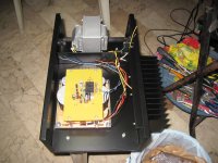
@number7, you have a long ways to go.... build the boards, build the chassis and psu and then we can tackle your build in more detail...
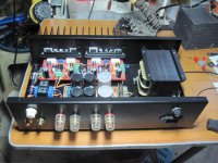
photos of my actual builds, they are very quiet, no hum.....
photos of my actual builds, they are very quiet, no hum.....
Attachments
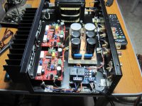
For me, the (T) looks like a head of a screw. Maybe there is a t-nut to the metal enclosure in the original design?!
That's a lie.
Are you as a Moderator setting an example to other Members that they can behave like you are now showing?
of course not...i just do not take you hook line and sinker....and why should i?
I agree.Speaker return should run along the amplifier output wire back to the amplifier board, then continue on to the main audio ground ...............
The speaker return and the speaker flow should be close coupled all the way back to the MAG.
That looks like a pretty competent design.Here is the circuit diagram:
An externally hosted image should be here but it was not working when we last tested it.
One point I am not sure about.
The voltage reference for the VAS cascode is shown coupled to Power Ground.
Should the V Ref be taken from the supply rail? i.e. swap the resistor R17 and Zener D3 and swap R18 for D4.
The two resistors 17 & 18 could be combined without any connection to power ground.
Last edited:
Speaker return should run along the amplifier output wire back to the amplifier board, then continue on to the main audio ground ......
i don't agree....i do it my way, never had any problem....
@number7, you have a long ways to go.... build the boards, build the chassis and psu and then we can tackle your build in more detail...
photos of my actual builds, they are very quiet, no hum.....
Not as far to go as you think 😉 Just not happy with the performance yet.
Class A Monoblock Power Amplifier - Product Design Showcase
Not as far to go as you think 😉 Just not happy with the performance yet.
Class A Monoblock Power Amplifier - Product Design Showcase
whoa....you remind me of Peter Daniels, are you him?
this thread should be in the vendors'.....
Who? What?
This is a very strange forum. I just wanted a simple answer to what I thought was a simple question.
This is a very strange forum. I just wanted a simple answer to what I thought was a simple question.
The problem is a faint hum - which I do not know if it is being caused by grounding problems, board layout problems, or the hum gremlins.
Who? What?
This is a very strange forum. I just wanted a simple answer to what I thought was a simple question.
sorry, your workmanship is very simmilar with him....a very good diy'er...
The problem is a faint hum - which I do not know if it is being caused by grounding problems, board layout problems, or the hum gremlins.
could be a mixture of those...
are you selling those amps?
Those are great looking amplifiers! Hum can be tough to locate. It's best to take a divide and conquer approach to locating it. First operate the amplifier out of chassis spread out on a work bench, and get it to operate silently there, then put it into the chassis and try to do the same. Spread out on the bench you won't be as susceptible to picking up hum from the transformers, and it will be easier to see if the layout is causing it, or poor PSSR, poor wiring ect.
How big is the Hum+Noise voltage? A DMM set to 199.9mVac will measure H+N sufficiently well to see how bad, or good, it is and will also let you assess what difference any change you make has to the measurement.The problem is a faint hum - which I do not know if it is being caused by grounding problems, board layout problems, or the hum gremlins.
Bad is anything higher than 0.5mVac
Good is <=0.1mVac, if you have normal speaker sensitivity. Those with very sensitive speakers can need less than 0.05mVac to make noise inaudible
If you have checked for zero output offset you can use headphones to assess Hum+Noise, but it's only subjective.
If you have some output offset, then a DC blocking capacitor can be used to protect the headphones. 1000uF+1000uF (back to back) for high impedance phones.
- Status
- Not open for further replies.
- Home
- Amplifiers
- Solid State
- Grounding question