Hi,
I've never built an Apex power amp so looking through this thread the A9 and AX11 seem to be popular so I decided to send (very soon) the Gerbers to the PCB manuf. so I can have my own.
These PCB layouts were donated freely. (see attached Layout from Sonal Kunal and Thiagomogi, thanks guys)
I just realized that my power transformer are about +/-39Vac, 300Va, I've got 4 of them and I'd like to use them of course. This 78Vct translate to about +/-53Vdc so too high for the normal A9 and AX11. Can I use these nice PCB layout and change a few components to make them work at +/-53Vdc ?
If so, what should be changed ??
If not, my solution would be to make a bipolar buffered zener regulator a la Zen Part 3 from NP.
Thanks a lot,
Eric
You can use regulated PSU from thread http://www.diyaudio.com/forums/solid-state/173462-studio-reference-amplifier-2.html
Regards
Great recommendation but is there a Gerber file somewhere ?
Maybe someone has a few boards laying around they are will to give or sell.
Thanks,
Eric
Maybe someone has a few boards laying around they are will to give or sell.
Thanks,
Eric
Hello everbody.
I need Fx8 bimo mod pcb files , gerber or sprint.
Thanks 🙂
Look in Index of Apex Directory thread:
http://www.diyaudio.com/forums/solid-state/292226-directory-apex-audio-amplifiers.html
Zero Negative Feedback Preamplifier
Nice one! 🙂
Will have to add it to the Index Chapter 2...
hi guys and special hi for mr mile😀
i want build sr150 and i have a question
how much maximum dc voltaje for sr150 on 4 and 8ohm speaker whit 1pair output transistor?
respectfully
i want build sr150 and i have a question
how much maximum dc voltaje for sr150 on 4 and 8ohm speaker whit 1pair output transistor?
respectfully
hi guys and special hi for mr mile😀
i want build sr150 and i have a question
how much maximum dc voltaje for sr150 on 4 and 8ohm speaker whit 1pair output transistor?
respectfully
Use +/-35V or +/-50V
Regards
Hi,
I've never built an Apex power amp so looking through this thread the A9 and AX11 seem to be popular so I decided to send (very soon) the Gerbers to the PCB manuf. so I can have my own.
These PCB layouts were donated freely. (see attached Layout from Sonal Kunal and Thiagomogi, thanks guys)
I just realized that my power transformer are about +/-39Vac, 300Va, I've got 4 of them and I'd like to use them of course. This 78Vct translate to about +/-53Vdc so too high for the normal A9 and AX11. Can I use these nice PCB layout and change a few components to make them work at +/-53Vdc ?
If so, what should be changed ??
If not, my solution would be to make a bipolar buffered zener regulator a la Zen Part 3 from NP.
Thanks a lot,
Eric
I made simulation of AX11 topology using +-90VDC. It tested my my friend, he claimed it have good sound quality. If you interested, I can make AX11 simulation using +/-53VDC.
I had never made a layout for the "100W ultimate fidelity Amplifier-AX-14", there are many many interesting designs by various guys + Mr. Mile's compact layout.
Anyway here it is, similar to the FR-100 layout I did and is based on the attached schematic early on in this thread. Its compatible to adding more pairs easily by minor modifications, only in o/p stage of the layout.
regards
Prasi
Anyway here it is, similar to the FR-100 layout I did and is based on the attached schematic early on in this thread. Its compatible to adding more pairs easily by minor modifications, only in o/p stage of the layout.
regards
Prasi
Attachments

Last edited:
I had never made a layout for the "100W ultimate fidelity Amplifier-AX-14", there are many many interesting designs by various guys + Mr. Mile's compact layout.
Anyway here it is, similar to the FR-100 layout I did and is based on the attached schematic early on in this thread. Its compatible to adding more pairs easily by minor modifications, only in o/p stage of the layout.
regards
Prasi
slightly revised with film i/p cap (15mm pitch like epcos 10u/63V)
Attachments
Last edited:
I made simulation of AX11 topology using +-90VDC. It tested my my friend, he claimed it have good sound quality. If you interested, I can make AX11 simulation using +/-53VDC.
Hi Bimo,
That would be very nice of you 😀
Will I be able to use the attached Layout ? (I already have the Gerber)
Thank you,
Eric
Attachments


Hi Bimo,
That would be very nice of you 😀
Will I be able to use the attached Layout ? (I already have the Gerber)
Thank you,
Eric
You have must be make the layout yourself. Because, it is slightly different than AX11 which originally using 35VDC. It is more like my modification of AX11 that built by someone here. For using +-53VDC, I will make the modification as simple as possible, but still have good specification.
Attachments
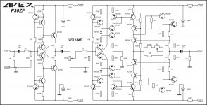
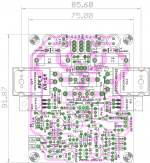
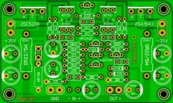
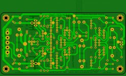
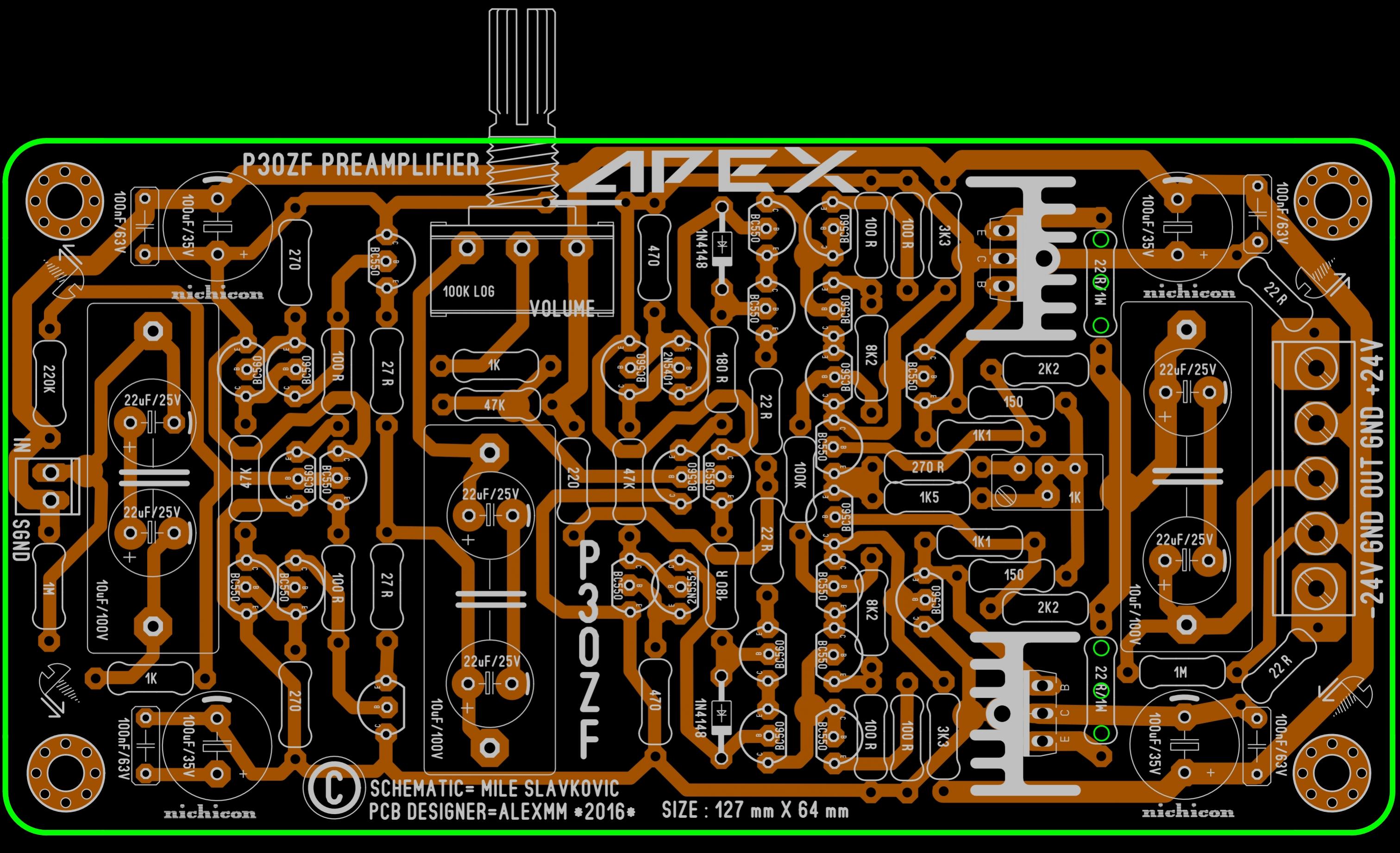
the master is back with a bang!.. wow!P30ZF preamplifier PCB layout ,not tested ..... 🙂
Regards,Alex
the master is back with a bang!.. wow!
Yep, where prasi could very well be the master of Eagle around here, I think Alex could very well be the Sprint master.😀
P30ZF preamplifier PCB layout ,not tested ..... 🙂
Regards,Alex
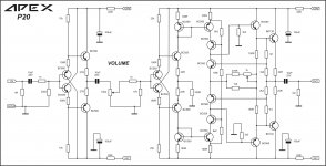
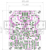
Hey Alex,
Very cool! A new circuit to build.

I am in the process of finally mounting my P30, built on your layout, into a case. I have the A class PSU built for it. The only thing I'm lacking is the MM28 phono circuit. If you get to feeling ambitious would you give a stab at a layout for it? I would love to have the complete setup. Here's the schematic.
Thanks, Terry
Attachments

- Home
- Amplifiers
- Solid State
- 100W Ultimate Fidelity Amplifier