Volume Conflict Caps on Reg Board
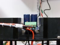
During a trail fit we found that the caps on the regulator board are standing out too far ( by about 8mm) so we will not be able to close the top covers of the amps.
We could swap them for ones with less body lenghts of course but I am wondering if others have encountered that problem as well or if we did something wrong. The caps are according to the power supply BOM ( Digikey No. 10305-ND, 35V, 1000uF, 25mm body length).
The standoffs holding the PCB are 10mm high as specified.
Clues what we might have done wrong are appreciated.
Markus
Attachments
My 35V 1mF are 22mm tall.
35V 220uF are 16mm tall.
I doubt you can find 1mF that will be 8mm shorter (17mm tall) and still fit in the diameter spacing available.
Is there a way to drop the assembly down into the U channel?
35V 220uF are 16mm tall.
I doubt you can find 1mF that will be 8mm shorter (17mm tall) and still fit in the diameter spacing available.
Is there a way to drop the assembly down into the U channel?
Last edited:
This has been discussed 3 years ago :
http://www.diyaudio.com/forums/pass-labs/208880-f5x-euvl-approach-build-thread-14.html#post3578696
You may use Mouser 647-UVZ1V102MHD or 647-UKW1V102MHD.
My apologies again,
Patrick
http://www.diyaudio.com/forums/pass-labs/208880-f5x-euvl-approach-build-thread-14.html#post3578696
You may use Mouser 647-UVZ1V102MHD or 647-UKW1V102MHD.
My apologies again,
Patrick
Andrew, thanks for your remarks. I already checked if I could lower the PCB but the FET underneath only allows for 4mm at best, that´s not enough.
Patrick, may I ask if you could kindly commend on the design considerations that have led to 1mF caps? Two aspects came across my mind, filter bandwidth which is not effective when the zener voltage is reached or voltage ramp-up time constant during start-up. If the later applies I guess I could easily reduce the cap value by a factor two or three.
Markus
You can reduce by a factor of 2. You can also increase the resistor by 2x to retain the fo of the LPF.
But the caps I listed above will also fit, as the others have already tried.
Whether the Zener is regulating depends on your MOSFET Vgs, load current and your transformer output voltage (which varies from example to example).
It is there in any case to make sure the caps downstream does not see over-voltage.
And the Zener voltage noise is still filtered by the second R-C.
Patrick
Patrick, what is the design temperature for the cap multiplier heat sink? Mine sits at 78 degrees, is it a bit too adventurous? It's hot today.
Thanks,
Davide
Thanks,
Davide
Should be around 65°C.
How much voltage are you dropping across it ?
The quickest way round is to reduce a bit of bias (to say 1.5A per FET).
Patrick
How much voltage are you dropping across it ?
The quickest way round is to reduce a bit of bias (to say 1.5A per FET).
Patrick
Way too much.
Better raise the output voltage by 2.5V.
And let the main heat sink drop an additional 2.5V per FET.
You can then reduce the regulator sink temperature rise by 50%.
And the main heat sink dissipation only increases by 16%.
Patrick
Better raise the output voltage by 2.5V.
And let the main heat sink drop an additional 2.5V per FET.
You can then reduce the regulator sink temperature rise by 50%.
And the main heat sink dissipation only increases by 16%.
Patrick
You can then reduce the regulator sink temperature rise by 50%.
Patrick
Reducing the voltage drop across the FET from 5V down to 2.5V means taking the Zener diode out, such that the device always operates in cap multiplier mode and never in regulator mode. But even then you would not get 50% reduction of the power dissipation. Don´t forget the dissipation of the rectifier diodes underneath. They drop also 1.4V. So you get 40% reduction of the dissipation at best. If you leave some voltage headroom for the regulator mode, say 1V, then approx 25% reduction of the dissipation is the best you could hope for.
As for temperatures. Well, the regulator board head sinks are not sorrounded by room temperature conditions. The thermal environment seen by regulator heat sink is defined by the amplifier´s outside heat sinks which operate at say 60degC. This is the reference temperature for the regulator heat sinks. So when 80degC are measured at the reg board and then the dissipation is reduced by optimistic 50% then the temperature drops also by 50% w.r.t. the outside heat sinks, by 10K from 80degC to 70degC. Of course this a very coarse simplification of distributed thermal problem and a pessimistic calculation but it shows that the termal problem cannot be solved that easily.
Davide I am wondering if you could kindly report the temperature reduction if the zener diode is just tanken out for a test?
I am currently considering other alternatives to solve thermal issue of the regulator board. One is using Complementary Darlington BJTs instead of FETs.
Markus
The thermal performance fulfils all the design requirements set out at the start.
http://www.diyaudio.com/forums/pass-labs/208880-f5x-euvl-approach-build-thread-19.html#post3888245
http://www.diyaudio.com/forums/pass-labs/208880-f5x-euvl-approach-build-thread-19.html#post3888251
I do not consider 66°C heat sink temperature excessive.
Especially when it is a TOP3 device dissipating 12W as designed.
Of course you are all smart engineers and you are most welcome to change whatever to your liking.
Cheers,
Patrick
Last edited:
Let me put the bias down and then we see where we stand. My was a bit of an extreme case, higher Ac voltage, 28 degrees surrounding air, 2 A bias. That said, the amp has been like this for more than three years.
When I tuned the cap multipliers, I tried to replace the zener with TL431 + pot, but for reasons I did not investigate at the time I did not succeed. (I was eager to put it into service) This mod would leave flexibility to tune the heat dissipation moving heat from one place to another. I might try it again. I suspect that the reason it did not work was insufficient capacitance at the output of the reference.
D.
You need at least 22uF at the output of a TL431.
But just try to remove the Zener altogether (if the caps downstream will take the voltage).
The MOSFET will drop 2.4V. Your ssink temperature should go back to design value.
Patrick
But just try to remove the Zener altogether (if the caps downstream will take the voltage).
The MOSFET will drop 2.4V. Your ssink temperature should go back to design value.
Patrick
diode spacing
Can anyone tell me the spacing for the diodes on the heatsink?
After discovering the quasimodo thread I am looking to snub the transformers as well as replacing the diodes. Pre-building the bridges (PTP) would reduce the time the amp is out of commission. Anyone snub the primrose tx with the quasimodo?
Attachments
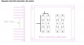
Don't you have the mechanical parts from which you can measure ?
Off my head I think 50mm, but I don't have the drawings with me right now to check for you.
Patrick
Off my head I think 50mm, but I don't have the drawings with me right now to check for you.
Patrick
- Home
- Amplifiers
- Pass Labs
- F5X -- the EUVL Approach - The Build Thread