CFA is here alive and singing under full quarantine up to now!
Looking good! Nice setup.
Big NS boards don't experience those issues we just saw on the mini boards.
But please, if you connect the speakers - use some DC offset protection. We never know in advance, when we may need a reserve 😉
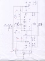
Unfortunately an accident occurred when i tried to change the feedback capacitor from 4u7 to 2u2 in servo circuit.
Now the lamp glow brightly.
May be the input transistor pair is death.
Strange is that when tested using diode test this measurement seems to be ok.😕
Now the lamp glow brightly.
May be the input transistor pair is death.
Strange is that when tested using diode test this measurement seems to be ok.😕
Attachments
Last edited:
What are the symptoms? DC offset? Oscillation?
It would make sense to fix the IPS board standalone - just safer.
It would make sense to fix the IPS board standalone - just safer.
The symptom is that offset start to rise from 1v to 10v d.c.What are the symptoms? DC offset? Oscillation?
It would make sense to fix the IPS board standalone - just safer.
Is it safe to desolder the R3=100K to stop the offset voltage?
Last edited:
The symptom is that offset start to rise from 1v to 10v d.c.
You interacted with the servo - probably some liquid could be left on the board... just guessing.
I also recommend to disconnect the load for the time being if you test with OPS - this will eliminate the current through the load, caused by the offset.
Valery.everything is clean.You interacted with the servo - probably some liquid could be left on the board... just guessing.
I also recommend to disconnect the load for the time being if you test with OPS - this will eliminate the current through the load, caused by the offset.
I haven't any load connected ,no input signal when testing offset.
Do you think that is useful to place a 4u7 again here just in case...
Last edited:
If the cap is good - there's no difference except the time constant. But you can try to return to the working configuration.
What about R3 lifting?If the cap is good - there's no difference except the time constant. But you can try to return to the working configuration.
What about R3 lifting?
Also possible for a test. -5V there means something is really wrong.
Yes but what?Also possible for a test. -5V there means something is really wrong.
This measurements taken with +/-15v presence only.
Keep in mind that AD711 has been changed with a new one.
The feedback circuit won't be operating without the high voltage rails connected along with the 15V rails.
The feedback circuit won't be operating without the high voltage rails connected along with the 15V rails.
Sure but the input pair?
The input pair will run, but nothing will balance the input board if the VAS transistors aren't operating and providing feedback to the input.
I will try again using 4u7.The input pair will run, but nothing will balance the input board if the VAS transistors aren't operating and providing feedback to the input.
This was a functional IPS before capacitor change.
To see what happened IPS separated from OUT and connected alone.
When R3 lifted everything is fine,except the offset voltage.With R3 lifted offset= 70mV.
Pin 6(out) of AD711 is at the rail voltage=13V.
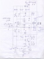
As the AD711 was changed it is clear that something in this offset contol circuit is faulty ....what? Pin 2 is on gnd connection due to LL4148 sorted(faulty).
Two new diodes and the problem is gone.
When R3 lifted everything is fine,except the offset voltage.With R3 lifted offset= 70mV.
Pin 6(out) of AD711 is at the rail voltage=13V.
As the AD711 was changed it is clear that something in this offset contol circuit is faulty ....what? Pin 2 is on gnd connection due to LL4148 sorted(faulty).
Two new diodes and the problem is gone.
Attachments
Last edited:
To see what happened IPS separated from OUT and connected alone.
When R3 lifted everything is fine,except the offset voltage.With R3 lifted offset= 70mV.
Pin 6(out) of AD711 is at the rail voltage=13V.
As the AD711 was changed it is clear that something in this offset contol circuit is faulty ....what? Pin 2 is on gnd connection due to LL4148 sorted(faulty).
Two new diodes and the problem is gone.
Interesting... what could make the diodes, withstanding up to 200mA of forward current, become shorted... Some potential on the soldering iron? 😱
D3 and D4?
Interesting... what could make the diodes, withstanding up to 200mA of forward current, become shorted... Some potential on the soldering iron? 😱
Yes D3,D4.
What could make the diodes......mine fault!
Trying to change the 4u7 the low voltage +/-15v has been left to on,i seen a spark. I assumed that AD711 was death and a new one has been installed. Finally the faulty part was the diodes.😱
- Home
- Amplifiers
- Solid State
- Revisiting some "old" ideas from 1970's - IPS, OPS