Mine has been auditioning, well received as hifi or clean instrument amp.
If need true stereo then make as monoblocs.
http://www.diyaudio.com/forums/lounge/296192-no-home-hybrids.html#post4822460
here is link in lounge area as there is no hybrid thread area.
Hybrid 12au7 - tpa3116 PBTL is the sweetest thing I've ever heard.
Any sound examples? Looks interesting.
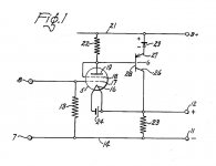
I stole it from this old 1958 patent.
https://www.google.com/patents/US30...ved=0ahUKEwifg6SauI3PAhXh7YMKHTz9BlgQ6AEIHDAA
Its basically the same ckt with a few improvements.
Yep I'm using the cheap $5.00 - 10.00 Tpa3116 mono boards until i can do the layout.
-
https://www.google.com/patents/US30...ved=0ahUKEwifg6SauI3PAhXh7YMKHTz9BlgQ6AEIHDAA
Its basically the same ckt with a few improvements.
Yep I'm using the cheap $5.00 - 10.00 Tpa3116 mono boards until i can do the layout.
-
Attachments
Any sound examples? Looks interesting.
dont think it would get through as set up.
i have a song listen to frequent, mp3 320k tested using same speakers KEF UniQ Q10 but two in parallel for 3 ohm load.
i can now hear a cymbals track had never noticed before.
Also no 'fatique' after many hours listening.
The tilt stack is super. Everyone finds a sweet spot.
Looking at the schematic a little more closer now, is there much of an advantage going with a split supply?
Oh, was thinking of a guitar track not audio.
Oh, was thinking of a guitar track not audio.
Hmm, I like the idea. But work is killing me lately. Feel like I would need a layout picture in addition to the schematic before attempting anything. I have 12Au7s and the TPA boards are cheap so I like the idea. The problems is that I would want to do a stereo build.
I got a reply from Pat Quilter regarding what's in his "Steelaire" amplifier:
"We did make an improvement almost a year ago. We upgraded the opamps to OPA1654 which are the quietest available FET-input devices. The previous generation used TL-074 opamps which have a standard noise figure. The improvement is about 8dB. Our Class-D amplifier is our own design, built for more rugged service than the consumer-grade ICE Power modules.'
"We did make an improvement almost a year ago. We upgraded the opamps to OPA1654 which are the quietest available FET-input devices. The previous generation used TL-074 opamps which have a standard noise figure. The improvement is about 8dB. Our Class-D amplifier is our own design, built for more rugged service than the consumer-grade ICE Power modules.'
ya thats the main complaint on using D.
I talked to a large music store that is privately owned about doing own label head amp.
I have to prove they wont smoke as some of the early D designs.
User and/or local dealer board repair is very desirable too.
The power limiter is crucial.
So a tpa3116 pbtl will limit around 35 watts in my design.
No op amps or global feedback at least in the pre.
Thats suprising he told you about a specific part.
-
I looked at the patent page you posted...he references some patents by Erik Pritchard (US5636284 * Feb 25, 1994 Jun 3, 1997 Pritchard; Eric K. Solid state emulation of vacuum tube audio power amplifiers) and I should try out a Quilter amp just to check it out because I Have a Pritchard Sword of Satori amp - all SS - and I used it last weekend at a gig and it just killed. You would never know it has not tubes, and I sure can't tell the difference. In fact, I think it sounds better all by itself than my Marshall (1977 JMP 50 Watt) does through a Marshall 4x10... I had a lot of fun playing through it again (I have too many amps...) and it FEELs tubey as well. Since I've never played a Quilter, I can't compare them but I will someday. The Pritchard takes pedals well, also, but I just played it straight (really, because one of the cables on my pedalboard flaked - didn't need anything extra, anyway). If you are looking at Quilters or other SS guitar amps, check out Pritchard as well. I am 66 and have been playing rock and roll for 50+ years so I'm not talking out my ***, just in case you were wondering... Erik is a really nice guy, too. YES ! - Wow, I just looked at his site and there is quote from me right up front... Nice!

The clipping cell circuit of modern Quilter amps...
...was employed already a few decades ago in the Pignose 30/60 amplifier.
Pignose Industries didn't really design or build their products, they simply outsourced them from other companies, which in this amplifier's case happened to be Quilter. Yes, before there even was this QSC Patrick started the venture by building guitar amps. Now he has returned to his roots.
Sharp individuals also notice the grounded output -scheme, which QSC made famous.
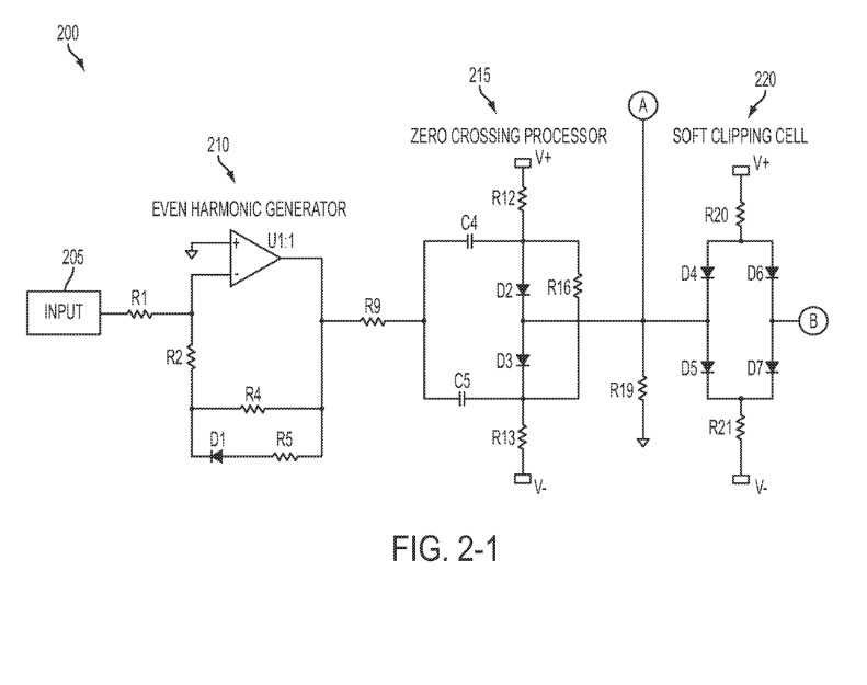
Anyway, what we have there is a clipping cell where diodes are referenced to - not ground - but voltage potentials in order to modulate overall clipping thresholds to some other values than approximately 600mV of a generic forward-biased (ground) shunt diode. Like in generic diode clipping circuits input signal's amplitude varies diode state between forward and reverse bias, which in turn generates amplitude distortion. First diode cell produces gradually increasing crossover distortion under continuos overdrive, second clipping cell is for peak clipping. Intogether the clipping characteristics resemble those introduced by an ovedriven tube class-AB power amp, which peak clips and begins to introduce gradually increasing crossover distortion under sustained overdrive condition.
Some may have also noticed "current feedback" employed in the power amp. It artificially increases output impedance of the amp, which decreases amp's damping factor. Frequency response becomes more dependent on load characteristics, which in case of dynamic loudspeakers are far from being purely resistive. Increasing inductance at higher frequencies, and resonant frequency of the driver, both cause significant gain boost at associated frequencies. This is another characteristic of generic tube power amplifiers, since many of them inherently have high-ish output impedance.
So in essence we have a quite realistic analog tube emulation circuit in there, which ironically is almost 40 years old already. Ironically, because all these modern tube emulation circuits in Peavey, Vox, Roland, etc. amps still revisit these very same old ideas. Don't believe the common folklore that "tube emulation" is a modern fad, or that astoundingly realistic methods to emulate tubes were not employed in transistor amps, which you could technically regard "vintage" by now. You'd be amazed how clever circuitry some rather old transistor guitar/bass amps incorporated.
Here's the complete modern Quilter -scheme:
What we see in the complete scheme is a clever addition, which is somewhat disguised by a drawing error: There are actually two different V+ and V- voltage sources. There are usual positive and negative supply rails with their "fixed" voltage, and then there are variably-regulated V+ and V- sources, coming from the regulator circuit depicted in the schematic.
So in essence the reference voltage potentials are no longer "fixed", they are interactively variable and voltage output of the reference voltage regulators decreases at signal peaks! Sustained overdrive condition will therefore gradually decrease clipping threshold as well, similarly to what happens when B+ supply "sags" in a generic tube power amplifier.
Speaker protection works by similar principle, I believe one of those resistors is selected to have thermal coefficient that causes regulator output voltage to decrease when the resistor heats up.
...was employed already a few decades ago in the Pignose 30/60 amplifier.
An externally hosted image should be here but it was not working when we last tested it.
Pignose Industries didn't really design or build their products, they simply outsourced them from other companies, which in this amplifier's case happened to be Quilter. Yes, before there even was this QSC Patrick started the venture by building guitar amps. Now he has returned to his roots.
Sharp individuals also notice the grounded output -scheme, which QSC made famous.
Anyway, what we have there is a clipping cell where diodes are referenced to - not ground - but voltage potentials in order to modulate overall clipping thresholds to some other values than approximately 600mV of a generic forward-biased (ground) shunt diode. Like in generic diode clipping circuits input signal's amplitude varies diode state between forward and reverse bias, which in turn generates amplitude distortion. First diode cell produces gradually increasing crossover distortion under continuos overdrive, second clipping cell is for peak clipping. Intogether the clipping characteristics resemble those introduced by an ovedriven tube class-AB power amp, which peak clips and begins to introduce gradually increasing crossover distortion under sustained overdrive condition.
Some may have also noticed "current feedback" employed in the power amp. It artificially increases output impedance of the amp, which decreases amp's damping factor. Frequency response becomes more dependent on load characteristics, which in case of dynamic loudspeakers are far from being purely resistive. Increasing inductance at higher frequencies, and resonant frequency of the driver, both cause significant gain boost at associated frequencies. This is another characteristic of generic tube power amplifiers, since many of them inherently have high-ish output impedance.
So in essence we have a quite realistic analog tube emulation circuit in there, which ironically is almost 40 years old already. Ironically, because all these modern tube emulation circuits in Peavey, Vox, Roland, etc. amps still revisit these very same old ideas. Don't believe the common folklore that "tube emulation" is a modern fad, or that astoundingly realistic methods to emulate tubes were not employed in transistor amps, which you could technically regard "vintage" by now. You'd be amazed how clever circuitry some rather old transistor guitar/bass amps incorporated.
Here's the complete modern Quilter -scheme:
An externally hosted image should be here but it was not working when we last tested it.
What we see in the complete scheme is a clever addition, which is somewhat disguised by a drawing error: There are actually two different V+ and V- voltage sources. There are usual positive and negative supply rails with their "fixed" voltage, and then there are variably-regulated V+ and V- sources, coming from the regulator circuit depicted in the schematic.
So in essence the reference voltage potentials are no longer "fixed", they are interactively variable and voltage output of the reference voltage regulators decreases at signal peaks! Sustained overdrive condition will therefore gradually decrease clipping threshold as well, similarly to what happens when B+ supply "sags" in a generic tube power amplifier.
Speaker protection works by similar principle, I believe one of those resistors is selected to have thermal coefficient that causes regulator output voltage to decrease when the resistor heats up.
SS, diodes, etc.
Thanks for the reply! I have worn my brain out the last few days digesting all I can find about tube emulation. I even spoke to Eric Pritchard again - been a long time. I've owned a lot of ss stuff over the years that promise to reproduce tube tone, feel, dynamics, etc. and the Sword of Satori is the only amp that has been able to stand with my Marshalls, Dr. Z's, H&K's, or any other bad-*** tube amp I've owned. I wonder if I can rent or borrow a Quilter to use with the band, which is where 'the rubber meets the road', so to speak. I have not played through a AX-FX II either so I don't know if that processor would work for me, either. Besides the tone, by which I think I mean balls and clarity without brittleness, the feel and response of the amp (or processor) is very important to me. If it won't clean up with just the guitar volume pot, I won't like it, which holds true for pedals, as well. Man, I Do love the search, although none of it is as important as just playing the guitar, which I do a lot with it unplugged...really nothing in the way then, just me and my fingers. Thanks again!
Mike
I looked at the patent page you posted...he references some patents by Erik Pritchard (US5636284 * Feb 25, 1994 Jun 3, 1997 Pritchard; Eric K. Solid state emulation of vacuum tube audio power amplifiers)e!
Think its the other way, Pritchard refs the 1958 patent, I did study his clipping ckts.
I was not too impressed really. They maybe ok for fuzz etc.
Redesigning my ckt for user overdrive adj.
No clipping devices, just programmable grid leak in second stage including compression effect.
Hi there!I would have asked @sneakermike about a schematic for Pritchard's amplifier , but he's not here for a few years already...although i saw his patents long ago , never saw a full schematic.I'd also be interested in seeing a modern Quilter guitar amp schematic if possible.The clipping cell circuit of modern Quilter amps...
...was employed already a few decades ago in the Pignose 30/60 amplifier.
An externally hosted image should be here but it was not working when we last tested it.[/URL]
Pignose Industries didn't really design or build their products, they simply outsourced them from other companies, which in this amplifier's case happened to be Quilter. Yes, before there even was this QSC Patrick started the venture by building guitar amps. Now he has returned to his roots.
Sharp individuals also notice the grounded output -scheme, which QSC made famous.
Anyway, what we have there is a clipping cell where diodes are referenced to - not ground - but voltage potentials in order to modulate overall clipping thresholds to some other values than approximately 600mV of a generic forward-biased (ground) shunt diode. Like in generic diode clipping circuits input signal's amplitude varies diode state between forward and reverse bias, which in turn generates amplitude distortion. First diode cell produces gradually increasing crossover distortion under continuos overdrive, second clipping cell is for peak clipping. Intogether the clipping characteristics resemble those introduced by an ovedriven tube class-AB power amp, which peak clips and begins to introduce gradually increasing crossover distortion under sustained overdrive condition.
Some may have also noticed "current feedback" employed in the power amp. It artificially increases output impedance of the amp, which decreases amp's damping factor. Frequency response becomes more dependent on load characteristics, which in case of dynamic loudspeakers are far from being purely resistive. Increasing inductance at higher frequencies, and resonant frequency of the driver, both cause significant gain boost at associated frequencies. This is another characteristic of generic tube power amplifiers, since many of them inherently have high-ish output impedance.
So in essence we have a quite realistic analog tube emulation circuit in there, which ironically is almost 40 years old already. Ironically, because all these modern tube emulation circuits in Peavey, Vox, Roland, etc. amps still revisit these very same old ideas. Don't believe the common folklore that "tube emulation" is a modern fad, or that astoundingly realistic methods to emulate tubes were not employed in transistor amps, which you could technically regard "vintage" by now. You'd be amazed how clever circuitry some rather old transistor guitar/bass amps incorporated.
Here's the complete modern Quilter -scheme:
An externally hosted image should be here but it was not working when we last tested it.[/URL]
What we see in the complete scheme is a clever addition, which is somewhat disguised by a drawing error: There are actually two different V+ and V- voltage sources. There are usual positive and negative supply rails with their "fixed" voltage, and then there are variably-regulated V+ and V- sources, coming from the regulator circuit depicted in the schematic.
So in essence the reference voltage potentials are no longer "fixed", they are interactively variable and voltage output of the reference voltage regulators decreases at signal peaks! Sustained overdrive condition will therefore gradually decrease clipping threshold as well, similarly to what happens when B+ supply "sags" in a generic tube power amplifier.
Speaker protection works by similar principle, I believe one of those resistors is selected to have thermal coefficient that causes regulator output voltage to decrease when the resistor heats up.
Do you happen to have this schematic? Link doesn't work.Here's the complete modern Quilter -scheme:
An externally hosted image should be here but it was not working when we last tested it.
What we see in the complete scheme is a clever addition, which is somewhat disguised by a drawing error: There are actually two different V+ and V- voltage sources. There are usual positive and negative supply rails with their "fixed" voltage, and then there are variably-regulated V+ and V- sources, coming from the regulator circuit depicted in the schematic.
So in essence the reference voltage potentials are no longer "fixed", they are interactively variable and voltage output of the reference voltage regulators decreases at signal peaks! Sustained overdrive condition will therefore gradually decrease clipping threshold as well, similarly to what happens when B+ supply "sags" in a generic tube power amplifier.
Speaker protection works by similar principle, I believe one of those resistors is selected to have thermal coefficient that causes regulator output voltage to decrease when the resistor heats up.
Thanks!
- Home
- Live Sound
- Instruments and Amps
- Quilter Amps