So do you worry about the resistor, or the value of the cap?
Hans
Hello, I'm very sorry if I didn't make it obvious. Its the capacitor value at 0.1uf as phase shift when the value on the label state 0.25uf. Anyway, i did some voltage measurement earlier and it looks spot on. The 3k resistor drops about 35V from 230V to 194 at each phase which I've no problem with that. The difference between the 2 windings is no more than 0.8V apart. When I applied 0.22uf , that winding shot up to 264V, a severe unbalance. I reverted to the previous value of 0.1uf. I'm feeling satisfied for now that the implemented circuitry is optimized.
Last edited:
Does your motor have 3 or 4 wires, and is the second phase generated by means of a capacitor connected to the motor drive signal.
If so, there is no technical difference with the other 2 phase motors in this thread.
When using amps that can deliver the 16 Volt with enough power, you can drive the motor directly without transformers.
Hans
It's a capacitor unit, plenty of wires 😉
But it doesn't perform like it use to. I may have to replace it even after I get this project done. All I need is a two channel sign wave generator like some of you are using, and a larger PSU. I've got a classD 50w thing laying around, TPA3116.
What sign wave generator are you guys using? (link?)
Hi Ralph
Started wiring things up and looking at last schematic you put 2k7 rest to .33 cap to ground and then did it again before rest to ground to create voltage divider. So you have 2 low pass filters back to back. Is this to create a steeper slope on the filter.
Did you see a better sine or something else which made you double up.
Thanks Tom
Hi Tom, the capacitors are probably not needed, but I wanted to reduce even further the harmonics from the generator, which are 50-60 db down on the output at 60Hz. Has was also correct in pointing out that the caps needed to be matched in order to avoid differing phase shifts between channels.
Question for guys who already use/test that circuit and also have same direct AC synchronous 2 phase motor as I am:
what is the max current draw (aprox)?
I’m not sure now sensitive that TPA3116 amp to V ripple, but my 24V 6.63A Lambda SMPS PSU has about 150mV ripple at half load.
PSU for Sine Gen is easy choice since it is anly 50mA.
Does PSU for that amp must be V-regulated one?
what is the max current draw (aprox)?
I’m not sure now sensitive that TPA3116 amp to V ripple, but my 24V 6.63A Lambda SMPS PSU has about 150mV ripple at half load.
PSU for Sine Gen is easy choice since it is anly 50mA.
Does PSU for that amp must be V-regulated one?
I had a bunch of Linn LP12 motors I rebuilt. At first taking the good bits to make complete motors. Then finding broken ends to resolder on the scrap ones. I think I had a 100 % rescue rate. The metal case will solder once the zinc removed. The LP12 motor is a reasonable one. It always struck me it could be rewound for 12 Vrms or less. Two TDA2050 type power op amps would do the job. I often wondered if they could be used as a Quadrature Oscillator. Having never found a design of that that worked well for me I never tried. A State variable Filter certainly could work. A TL071 for the 3 rd op amp. The old L165 would seem very suitable. It is happy at unity gain if inverting. I have driven a stepper on AC with it and had no problems.
I measured the THD of a LP12 motor and found about 8% used as a generator. A small resistor in-line shows this is typical of the how it is when working as a motor and steppers of the 7.5 degrees type not very different. A squarewave being not a lot worse as the motor dictates how this works. Thus phase and voltage are the prime considerations. I dare say a pre distorted wave could do something fed to the motor ( derived from the resistor showing the motor current ). It might slightly reduce vibration for a given power output. It will be the same every time unlike music. I am told a negative output impedance amplifers can work. I have no idea if true. The one who tried it said the positive feedback ( his words ) tuned with the motor in your hand. As I say no idea how it could be done.
BTW, Voltage out is the absolute prime factor when belt drive using synchronous motors. Hysterisis motors seem to have a self distortion rate of about 0.5%. These are more responsive to any improvement that can be made. Garrard, Thorens TD124,Lenco. It is possible to hear this by listening to these motors running with the platter off. It is very odd as they already seem perfect on dirty mains. The sound difference is not subtle.
3 phase VFD
Hi folks, just now became aware of this thread. I have been working on a 3 phase VFD for several months now, and have a working drive running a Papst motor, salvaged off an old Rek-O-Kut TT. It's nothing fancy, no feedback loop or anything like that.
It is based off of stuff I mostly bought on ebay, and uses the $40 3 phase signal generator mentioned earlier in this thread. It ended up costing me about $150 to build. It uses the brute force approach, and wastes a lot of power, but power is cheap these days, with class D amps and dual rail power supplies. I'm calling it Jethro, after the character Jethro Bodine in the old Beverly Hillbillies TV show. It's a simple brute, and also an example of "hillbilly engineering" , so think it fits. It uses the signal generator, 3 class D amps, three dual rail power supplies, and three torroid filament transformers, and a bunch of monkey coffin power resistors. Basically about 450 watts of potential driving a 30 watt motor. 🙂
As usual, I put the cart before the horse, and got fascinated with the motor before I actually built the TT. At this point I can't really totally evaluate the project, as I'm getting some slightly inconsistent results, while testing the motor unloaded. At this point I don't know if the inconsistencies are real, and if they are real, is the potential problem the signal generator, the motor, or the cheap tachometer I'm using to measure the speed.
I must warn everyone that I am completely self taught, and know very little about solid state circuitry. However I was an IBEW electrician (retired), and I am a somewhat accomplished tube amp builder and designer (self taught as well). I don't have a lot of technical knowledge, or sophisticated equipment, but that's never stopped me. Bear with me, and keep it in relatively simple terms please.
At this point, all I know is the motor runs smoother than on regular single phase and the faking capacitor, and has a LOT more torque. The precision instrument I used to determine this is my right index finger. It does change motor speed with frequency. Exactly how accurate the speed is, I'm not sure of, and will probably have to wait for the completion of the TT project, which unfortunately could take quite a while. At this point it seems very very close, but we are definitely NOT playing horse shoes or hand grenades, with TT drives accuracy is paramount.
Over the last few months I've been posting this on the Vinyl Asylum. I have been reluctant to post the construction details, and a bill of materials, since I didn't want people to waste time and money on a project that might not be ready for prime time. However, this forum is composed of more adventurous souls. If anyone might be interested in this, and may want to help develop it, or at least get some ideas. I'd be glad to share the method of my madness, and sources for materials, just let me know. I would also welcome any constructive comments or observations.
Here's a photo of Jethro in all his unsophisticated glory. BTW the amps and supplies seem to be very stable at the frequencies and voltages to run the platter between 33.33 and 45 rpm (~1800-2432 RPM on the motor). I'm not real interested in 78, probably a good thing as that motor would really be flying at that RPM.
Attachments
You guys need to start putting these things on metal boxes at some point... they're a pollutant of your audio system.
Ya I know... mine isn't even built yet.
Ya I know... mine isn't even built yet.
I hear ya
This was a PITA to build, so just planning on building a metal box around it and adding some quiet computer fans for cooling. I'm not going to take a lot of pains to make it real pretty, as I don't have the WAF to deal with, besides I like the mad scientist look. The power supplies have a low voltage section that will work for the fans. I will also place it some distance from sensitive equipment. I know it transmits a lot of noise, I can really hear it if I get it closer than 10 feet from my shop radio.
twystd
I always liked the hysterisis motor in how it could do most of this simply.I always fancied clockwork would be best. Or a lighthouse and long string ( 78's were cut like this in the early days ). If you do the maths for that even with a small bobin that's the sort of height you need to have a gravity motor. My better idea was a water wheel and water tank. It should have no cogging. Could be made to look neat. A turbine at the turntable centre. The speed by servo and magnetic brake.
BTW, just finished reading this thread, and learned a lot. I'll post a post, similar to the one I posted, on the Vinyl Asylum. It's pretty evident that ralphfcooke came up with a better project.
Thanks Ralph for the link. After reading through the thread it is evident that you came up with a similar approach, but from a practical viewpoint, a much better engineered project. Wish I would have known about this earlier. Oh well, looks like mine will work, just a lot less efficient. One thing I've learned, if you are not an engineer (and I'm definitely not) on the subject, when in doubt, over build, which obviously I did. Good work BTW.
I'm going to add some .47uf caps across the input like you did. I have some 4.7uf caps to block dc (there was a DC offset from the generator) in series with the signal, looks like I could benefit with one in parallel with the load to shunt the noise. The reason I used 4.7uf to block DC is I chose a cap that solved for a decade down (6hz) from the 60hz I was generating. I figure a decade down, and there won't be any significant phase shift. Not sure that is important or not, but easy enough to do. I also think my transformers (10va) need a higher VA rating. Looks like an upgrade is in order. Thanks again for the link, work, and info.
twystd
One thing about the input cap. Unlike most times a small cap gives you a 1st order high pass input filter. This can be useful if using 50 Hz mains and wanting 50 Hz. There is very often a beat frequency in the subsonic range. It isn't a cure, it helps not to make it worse. Careful DC PSU grounding is important. If the motor is AC coupled via capacitor it can do the same ( could be into the transformer ). As the conditions of this power supply never change it should be fine to do this. Also if wanting to do a speed change it can be useful to offset the inductance of the motor. For example Linn thought 66V 50 Hz ideal 33 1/3 driving from their 126 Vrms motor. I think 80 Vrms better. There is still scope to drive the 45 at 67.5 Hz and 105 Vrms lets say. I suspect it will work out this way and that inductance is dominant. The right cap allows this to be chosen without any fancy switching. AC coupling the output is also protection of the motor if no transformer used ( e.g. 24 V option where motor exists using what would be a 100 watt 8 R amplifier ). It might also improve the 10 VA transformers to help them this way. I suspect they are fine with a little care. NON polar caps exist if required in the 100's uF range. Get the output to drop a little. From 10 down to 8 V rms starts to look about right. Then restore it to the original by increasing the input to the amplifier. It avoids the transformer being asked to look at subsonics without an oscilloscope on hand to confirm the advantage. The capacitor should be outside of any feedback loop. If the cap is for loudspeakers it should be fine. If not, be sure the ripple rating is OK. I would tend to use 33 uF and add them in various ways until the result arrives ( i.e. 3 in series is 11 uF, in paralell 99 uF ). I bought 100 for less than $7.
If you are in the 50/60 Hz range most transformers work in an ideal way. Up to 7 kHz most are usable. It is below 40 Hz where most have trouble and the motors more so if 50/60 type. The big ones less so in both cases. The 10 VA you use as long as not using low grade materials should be OK if not asked to do the impossible. The older style E & I types at lower cost at lets say < 20 VA seem worse. On a belt drive subsonics are removed by the belt. This will not show up much on technical tests. My hunch is better without it. Placebo perhaps. As a German guy said to me " we get right what we can ". This was when me saying why RIAA to +/-0.05 dB when the pick up might be + 7 db at 12 kHz.
A rough guide to motor torque is to measure the AC current to the motor. Often it drops when 45 RPM. Most meters are able to do this if in the 40 Hz to 1 kHz range.
I wouldn't connect this device to ground. The case can be. The output transformer should float also if used. No centre tap to ground either without a listening test.
Last edited:
Hey Guys
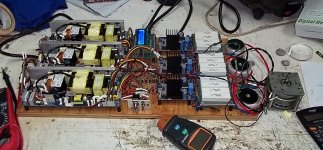
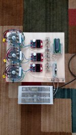
Got the power supply up and running. Built it like Ralph's schematic but with only one low pass filter and 3 ohm load resistors after amps.
I do not have a 3 phase motor yet so only using 2 phases at 90 degrees. Butttttttttt!!!!! Get this. I hooked it up to the turntable and the thing starts up at 60 hz it is running to fast so I go to frequency gen and adjust it down .1 hz at a time. Now for the problem at 58.9 58.8 and 58.7 it runs at 33.476 rpm at 58.6 58.5 and 58.4 it runs at 33.204 rpm. It is like it knows I want 33.333 and wants nothing to do with it. HOW CAN that happen???? This is beyond my pay grade. I am using a Phoenix Roadrunner so I can watch the rpm as I go. The controller is holding the rpm stable just not at the speed I need.
I can make another pulley or machine down the current one but something has to be wrong for there to be a large gap at 33.333 rpm.
Thanks Tom
Hi Tom,Hey Guys
Got the power supply up and running. Built it like Ralph's schematic but with only one low pass filter and 3 ohm load resistors after amps.
I do not have a 3 phase motor yet so only using 2 phases at 90 degrees. Butttttttttt!!!!! Get this. I hooked it up to the turntable and the thing starts up at 60 hz it is running to fast so I go to frequency gen and adjust it down .1 hz at a time. Now for the problem at 58.9 58.8 and 58.7 it runs at 33.476 rpm at 58.6 58.5 and 58.4 it runs at 33.204 rpm. It is like it knows I want 33.333 and wants nothing to do with it. HOW CAN that happen???? This is beyond my pay grade. I am using a Phoenix Roadrunner so I can watch the rpm as I go. The controller is holding the rpm stable just not at the speed I need.
I can make another pulley or machine down the current one but something has to be wrong for there to be a large gap at 33.333 rpm.
Thanks Tom
This against all odds. a synchrone motor has no alternative but to follow the frequency of the signal that is offered under the condition:
1) the phase between the different signals is correct
2) The voltage is adequate and is a sinewave
3) the phases have roughly the same voltage.
Your picture of a job well done shows 3 phases, but your motor has only 2 Phases, is that correct?
Why are you using 3 Ohm resistors, have you tried without or with a lower value, because quite a voltage drop will develop over this resistor.
In that light, what is the voltage when measured on the motor and are the phases equal in voltage?
Do you have a scope to measure the signals on the motor and are they neat sinewaves?
Just a number of questions.
Succes,
Hans
You must have a frequency counter to be sure that you have 59.9 Hz when you set 59.9 Hz on the generator, etc ...
Now for the problem at 58.9 58.8 and 58.7 it runs at 33.476 rpm at 58.6 58.5 and 58.4 it runs at 33.204 rpm.
With a pulley ratio of 18:1, the difference between 33.476 and 33.204 is a frequency change to the motor of ~0.5Hz, which would be right for 58.9Hz to 58.4Hz.
The platter speed should change ~0.055 RPM for each change in frequency to the motor of 0.1Hz. If it is not changing for 3 frequency steps, I would suspect that the generator is not capable of 0.1Hz steps. Are you sure this is DDS or is it PWM (or some other method)?
A frequency step of 0.1Hz is still too coarse IMHO. The VPI SDS was capable of 0.01Hz. Using DDS, I can get frequency changes as small as 35µHz.
Last edited:
Hi Hans / Bill / everybody.
OK here is latest. Put a hand held single phase scope (tpi scope plus 440). The voltage when the generator read 58.7 hz was 126.2 v on 1 and 126.7 on the other. The hz on the scope at the motor read 58.36 on both channels.
So retesting watching hz at the motor when you jump from 58.7 to 58.6 on the generator readout it jumps from 58.36 to 57.88 on the motor with scope and fluke hz counter. Maybe Bill is on to something with it being a course adjustment. Can the digital readout on the generator show a readout change without a real output change. It seems to really change every 3 to 4 .01 changes on the generator display.
Bill this generator is the one Ralph linked on post 28. It is called a sinusoidal signal generator. They do not comment on how they do it. You might know how they did it.
Hans the sinewave looks pretty good but it is hardly a state of the art scope. Is there anyway to check phase angle without a 2 channel scope.
So everything seems to be in order the rpm changes when the frequently at the motor changes. When the voltage go from 90 to 126 nothing changes. The mystery seems to be that the gen display shows .1 hz changes with no change at the motor until it jumps .5 at the motor.
OK if we find out that in real life this gen only adjusts in course steps is there a add on to make finer adjustment.
Thanks Tom
- Home
- Source & Line
- Analogue Source
- Optimally driving a (VPI) synchronous turntable motor