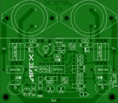
PCB is not tested!
hi BC109, thanks for pcb, 2 missing connection, r 36k to pin 3 and colector bc 516 to pin 5 ic
Tnx. Fixed. 🙂
Jumper can be remove...
Attachments

BC109, if you change order of components 2k7, 2k2, 1n, 1k and 100p from bottom to top, you don't need any jumper.
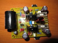
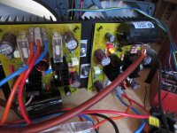
I built also Apex FX-8 bimo mod, pcb Prasi, great soft sounding amp with nice bass 🙂
Thats great, thanks for posting and nice diy style work with big coupling cap🙂.
regarding sound, thats what the opinions around here seems, nice hi-fi sounding with good bass... time to build for myself...
Reg
Prasi
Thats great, thanks for posting and nice diy style work with big coupling cap🙂.
regarding sound, thats what the opinions around here seems, nice hi-fi sounding with good bass... time to build for myself...
Reg
Prasi
thank you, sure it is worth a try!
... be aware of fake lats from aliexpress, ebay and similarly doubtful sources
😉
thank you, sure it is worth a try!
... be aware of fake lats from aliexpress, ebay and similarly doubtful sources
😉
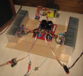
You could thermally couple the i/p pair for better offset stabilization. if measured, does it vary much in cold condition and hot condition? also what bias have you set it up?
reg
Prasi
You could thermally couple the i/p pair for better offset stabilization. if measured, does it vary much in cold condition and hot condition? also what bias have you set it up?
reg
Prasi
I can couple it. In cold is offset 2mV on one module and 3mV on second and hot condition I have not measured offset. In hot condition I set up bias to 150mA, cold it is about 130mA. 150mA it is little much, sure can be fewer.
FH9/FH11 adapted to each other
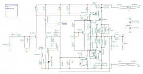
Most of the parts are the same for these 2 amps. So the idea was, to choose same part designators (R1, C1, etc) to same parts in layout as well as in the schematics and the BoMs.
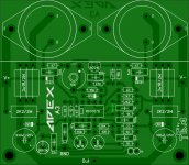
For people who need no minimized PCBs is there an advantage: You need only 1 PCB for 2 types of amps or you get a FH9 with adjustable DC-offset and a Thiele network on PCB.
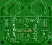
The changes in layout ar minimal: MPSA92 and MJE350 can be mounted alternatively.
The PCB is designed as a double side board (no additional costs at PCBWay), but bottom layer can be use only for one-side design.
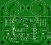
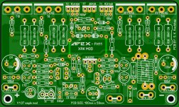
Right now I will first post a photo preview of the PCB and the schematic of the FH11. Don't hesitate to give a feedback if you will find any failure.
Soon will follow the BoM and the Gerber files! and, finally, I will do the same for the FH9(HV) design.
The version number for all is V1.07
Most of the parts are the same for these 2 amps. So the idea was, to choose same part designators (R1, C1, etc) to same parts in layout as well as in the schematics and the BoMs.
For people who need no minimized PCBs is there an advantage: You need only 1 PCB for 2 types of amps or you get a FH9 with adjustable DC-offset and a Thiele network on PCB.
The changes in layout ar minimal: MPSA92 and MJE350 can be mounted alternatively.
The PCB is designed as a double side board (no additional costs at PCBWay), but bottom layer can be use only for one-side design.
Right now I will first post a photo preview of the PCB and the schematic of the FH11. Don't hesitate to give a feedback if you will find any failure.
Soon will follow the BoM and the Gerber files! and, finally, I will do the same for the FH9(HV) design.
The version number for all is V1.07
Attachments
Nice work Eaglemaster!
Are you saying the board is double sided so by picking one side or the other you get either FH9 or FH11? How clever is that? 🙂
Are you saying the board is double sided so by picking one side or the other you get either FH9 or FH11? How clever is that? 🙂
Nice work Eaglemaster!
Are you saying the board is double sided so by picking one side or the other you get either FH9 or FH11? How clever is that? 🙂
Not really, xrk971, it is mainly the layout of FH11. But with a slightly different part-set (according to the particular BoMs), you can mount both amps on it alternatively (the part designators are the same).
Double side only to avoid 2 jumpers and to give the copper around the pads at the bottom side more stability for the soldering process.
P.S. the silk screen is FH11, so only a few part values can differ (therfore the BoM is mandatory) but ALL part designators are correct for both boards.
Last edited:
- Home
- Amplifiers
- Solid State
- 100W Ultimate Fidelity Amplifier